Configuring the EPW 400
OM 100.EPW 400.202002.en 85
Note: Firmware version EPW 400
Up to EPW
400 version V1.06 the outputs of switching points SP1-
SP3 are only updated while measurement is in progress.
From EPW
400 version V1.07 onwards, the outputs of switching
points SP1-SP3 are constantly updated.
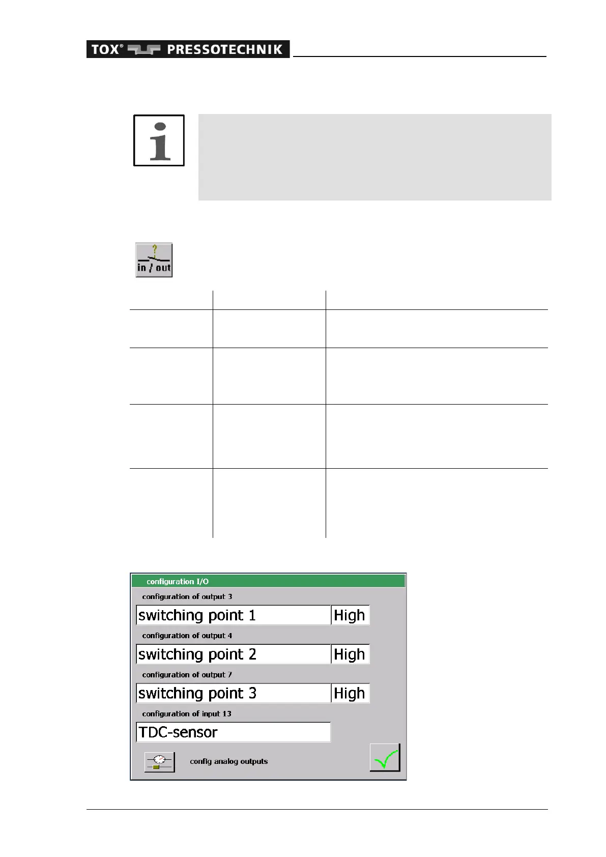
6.2.35 Configuration I/O
In this window you may fix the switching function of the digital outputs 3,
4 and 7 as well as of the digital input 13:
Refer to switching points
Change condition at NOK or reset
Refer to switching points
Change switching state if NOK,
For activation see 'Evaluation options'
Refer to switching points
counter
Change of the switching condition when
reaching the taught-in number in the order
counter, view counter or tool counter.
For activation see 'Evaluation options'
After activation, the user level can be se-
lected from a control system.
For activation see 'Evaluation options'
The switching logic can be switched between the settings 'High' and 'Low'.
 Loading...