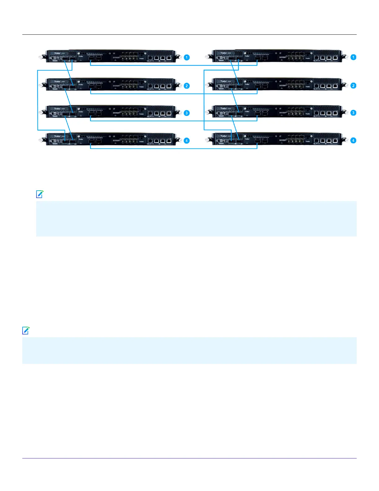
4. On the rear panel of each NS9500 Sensor, plug a RJ-45 cable in the Management port (labeled MGMT).
5. Plug the other end of the cable into the network device connected to your Manager server.
6. Create a failover pair using Manager's Failover Pairs page.
To connect the rst Sensor in the primary stack with the rst Sensor in the secondary stack, you can use either the
QSFP28 module (2x100 G) module or the QSFP+ (4x40 G) module. The QSFP28 modules support the DAC cables for
interconnect.
:
Scenarios for stacked NS9500 Sensors
This section explains about the scenarios for stacked NS9500 Sensors.
Scenario 1: Node failure
The examples in this section uses 4 node stack with 100 Gbps capacity. The scenarios are also valid for 2 node stack with 40
Gbps or 60 Gbps capacity.
In the event of a single or multiple node failure in a stack, the remaining Sensors continue to scan trac and a fault is generated
in the System Faults page in the Manager. You can view the status of the nodes in the stack in the Device Manager page.
Example 1: Single node failure
Trellix Intrusion Prevention System NS-series Sensor Product Guide
| NS9500 Sensors1
70
Note
Note



 To Next Page