Configuring
Hans Turck GmbH & Co. KG | T +49 208 4952-0 | F +49 208 4952-264 | more@turck.com | www.turck.com
18
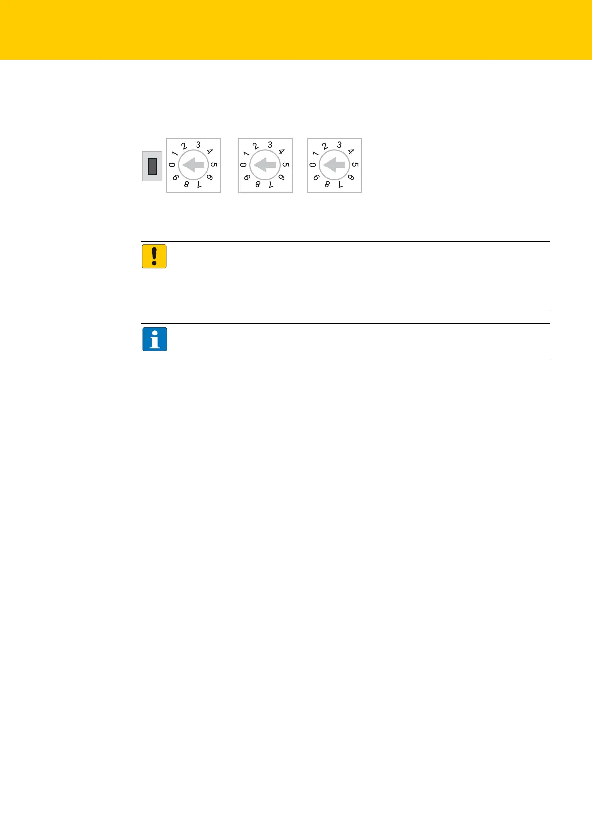
5.2 Address Assignment
Setting the address mode is done through the 3 rotary coding-switches on the gateway.
5.2.1 Mode: Static Rotary
When using the rotary-mode, the last byte of the station’s IP address can be set via the rotary coding
switches.
Switch position 000: in TURCK devices used to reset the device to the default IP address (see
Resetting the IP Address, Switch Position "000", page 20).
Switch position 001: normally reserved for the default-gateway
Switch position 002…254: valid IP address range
Switch position 255: normally used for broadcast messages in the subnet.
We therefore recommend addresses in the range of
002…254.
Fig. 2: Decimal rotary coding-switches for address setting
ATTENTION!
Protective cover opened
Protection class IP65/IP67/IP69K not guaranteed
Screw the protective cover over the switches firmly
Check if seal of the protective cover is correctly placed
NOTE
After every change of the address-mode, a voltage reset must be done.
x10
x1
000: 192.168.1.254
1 - 254: static rotary
300: BootP
400: DHCP
500: PGM
600: PGM-DHCP
900: F_Reset
x 100

 Loading...


