Mounting
Hans Turck GmbH & Co. KG | T +49 208 4952-0 | F +49 208 4952-264 | more@turck.com | www.turck.com
24
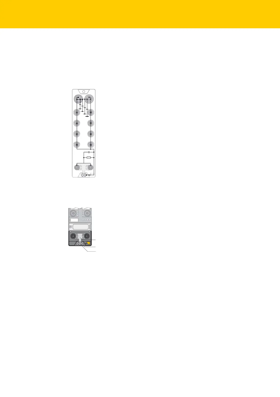
6.1 Grounding the Device
6.1.1 Grounding and Shielding Concept
The grounding and shielding concept of the TBEN-L modules allows the fieldbus and I/O parts to be
grounded separately.
The grounding clip (1) at the M12 connectors for the fieldbus connection (P1, P2) connects the
shield of the fieldbus lines.
The grounding ring (2) is attached below the grounding clip and connects the functional ground of
the 7/8" connector (pin 3) for the power supply with the functional ground of the M12 connector
(pin 5) for connecting the sensors and actuators.
The grounding screw (3) connects the device with the system's reference potential.
Fig. 5: Replacement wiring diagram, shielding concept
Fig. 6: Grounding components
1 nF
2,2 MΩ
X1
C0
C1
C2
C3
P1
X2
C4
C5
C6
C7
P2
4 x 15 nF
1
2
3

 Loading...


