Connecting
Hans Turck GmbH & Co. KG | T +49 208 4952-0 | F +49 208 4952-264 | more@turck.com | www.turck.com
28
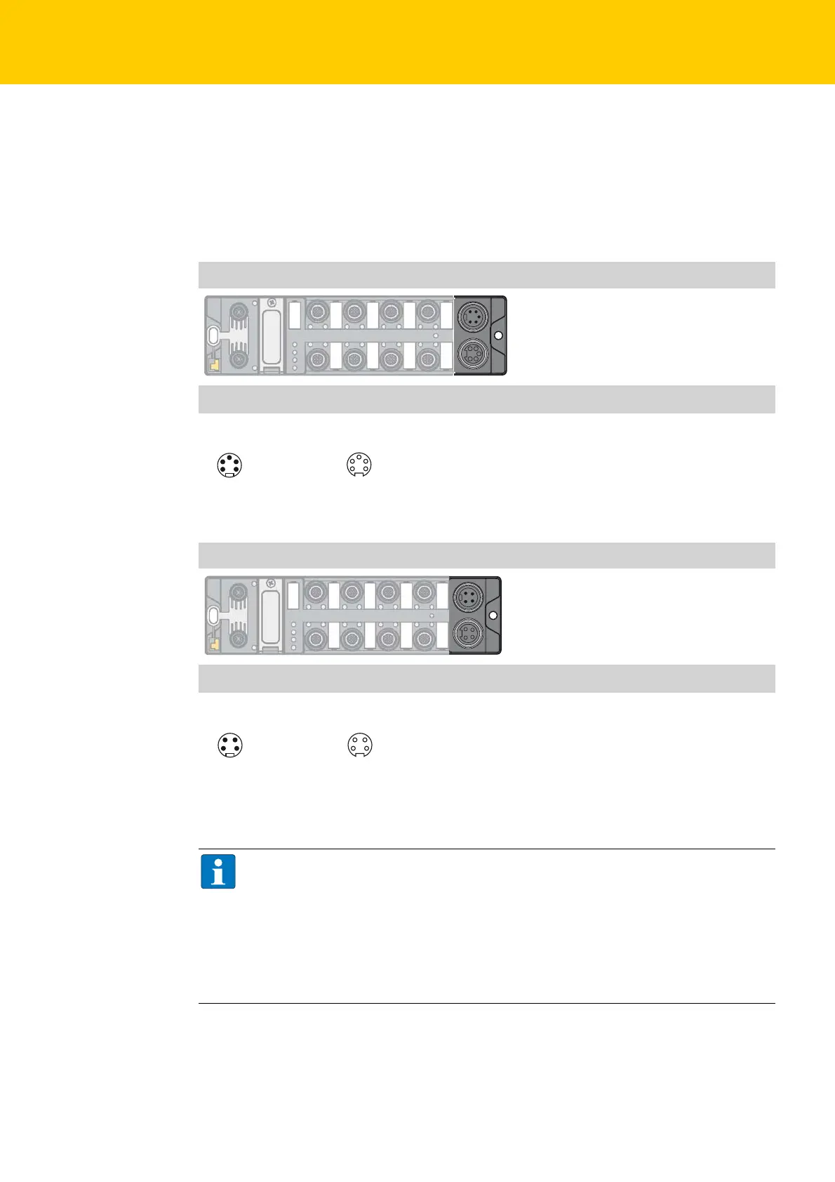
7.2 Connect Power Supply
For the connection to the power supply and the feeding through of the power, the device has two
5-pin 7/8" connectors.
The power supply connectors are designed as 4-pole (TBEN-L4) or 5-pole (TBEN-L5) 7/8" connectors.
V1 and V2 are galvanically isolated. The maximum tightening torque is 0.8 Nm.
Connect the device to the power supply according to the pin assignment shown below.
Supply voltage 7/8", 5-pole
Pin assignment
X1= voltage IN
X2 = voltage OUT for supplying the next node
V1 = supply voltage 1 (incl. supply of electronics)
V2 = supply voltage 2
Supply voltage 7/8", 4-pole
Pin assignment
X1= voltage IN
X2 = voltage OUT for supplying the next node
V1 = supply voltage 1 (incl. supply of electronics)
V2 = supply voltage 2
NOTE
V1 and V2 are fed and monitored separately. In case of an undercut of the admissible volt-
age, the connectors are switched-off according to the module's supply concept (see Sup-
ply concept (see Supply Concept, page 29).
In case of an undervoltage at V2, the "POWER" LED changes from green to red. In case of
an undervoltage at V1, the "POWER" LED is turned off.
The behavior of the LED POWER can be configured via the parameter "LED-behavior (PWR)
at V2 undervoltage)".
1 BK = V2 (–)
2 BU = V1 (–)
3 GNYE = FE
4 BN = V1 (+)
5 WH = V2 (+)
3
4
5
2
1
wv
3
4
5
2
1
X1 X2
wv
1
2
3
4
1 RD = 24 VDC V2
2 GN = 24 VDC V1
3 WH = GND V1
4 BK = GND V2
1
2
3
4
X1 X2

 Loading...


