3.CONNECTION
15
3-6-1. Connecting to Cage Clamp Terminal Block
The output terminal D/A option and RS-485 option is using the cage clamp system
terminal stand. Please connect in the following procedure.
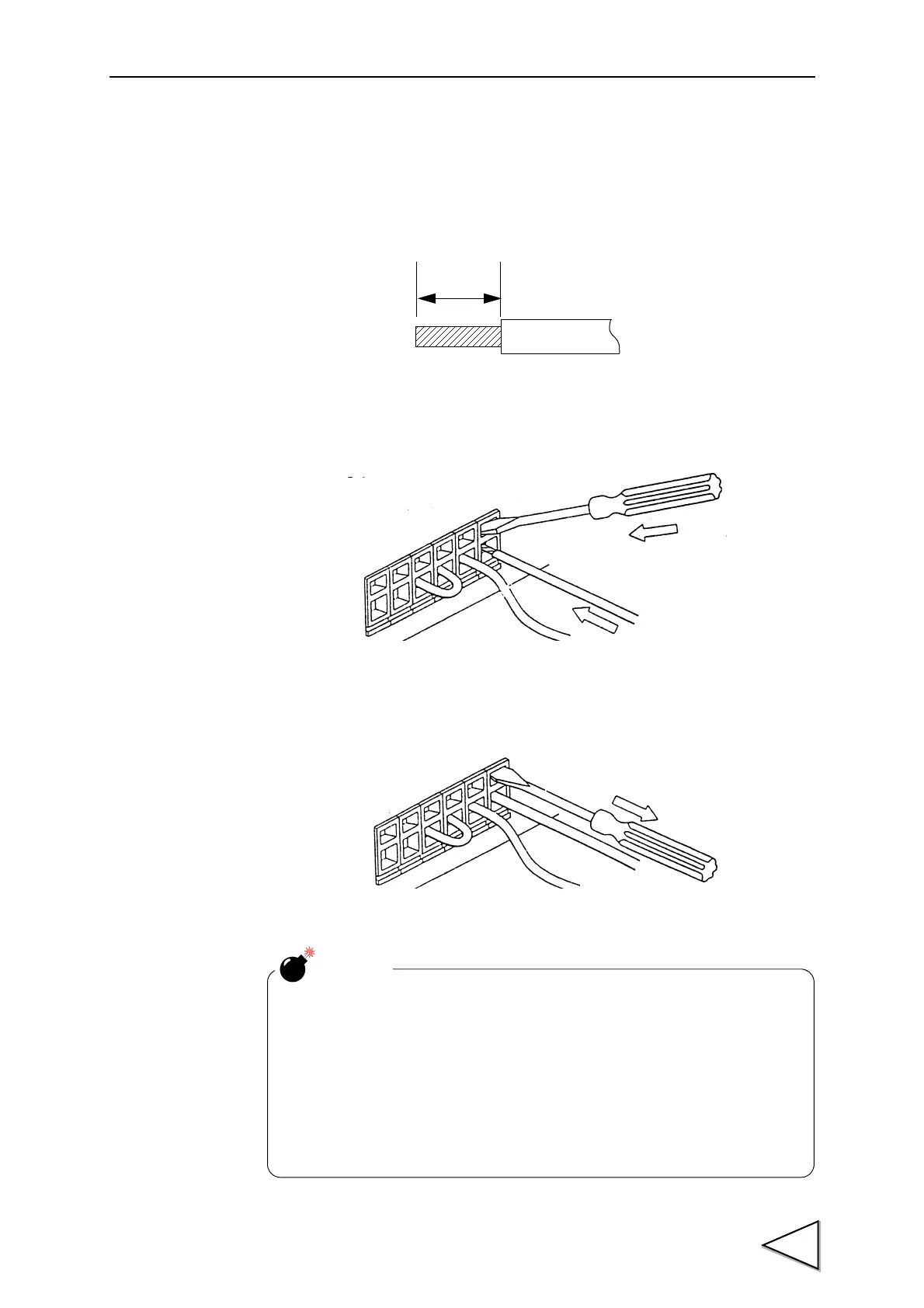
1.Strip the casing 0.2inch (6mm) on the cable to be connected.
2.Twist the bare wire to fit the terminal hole.
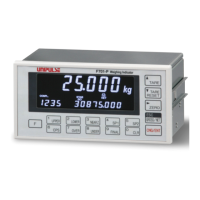
3.Insert the supplied screwdriver into the upper hole and lift upward.
4.Insert the twisted wires into the lower hole.
5.Make sure cable is clamped securely and does not come out with a slight tug.
CAUTION
・Cable can be from 24 to 14AWG (0.2 to 2.5mm
2
)
・ It is not necessary to solder the cable wires or to fix a solderless terminal.
・If several cables to be inserted to the same hole, twist those cable wires
together and insert.
・If you connect a cable (a load cell, SI/F, external input and output),
please turn off and be sure to perform the power supply of a main part.