13.RS-232C INTERFACE
82
13-1-2. Connector Pin Assignment
This connector connects the RS-232C.
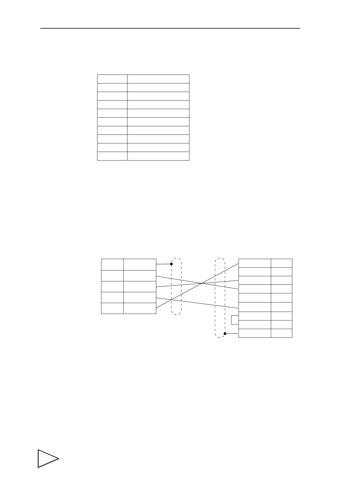
13-1-3. Cable
The following shows an example of connection between DTE-DTE terminals. This will
require modification depending on the equipment to be connected. For details, see the
instruction manual of the equipment to be connected.
* This connection diagram shows an example of connecting a DTE (data terminal
equipment) personal computer.
Use a straight cable for connecting a DCE (data circuit terminating equipment) such
as a modem.
* Before preparing a cable, check the connector shape and pin assignment of the
equipment to be connected again.
Pin No. Signal name
1
2TxD
3RxD
4DTR
5
6
7GND
8
Case F.G.
Case
F.G
2
TxD
3
RxD
4
DTR
7
GND
GND
5
DTR
4
TxD
3
RxD
2
(CD)
1
(DSR)
6
CTS
8
RTS
7
F.G
TCP8080-01-520
F371
D-sub 9 pin
Personal computer
, etc.
Cabling diagram
CA371-232 (optional)