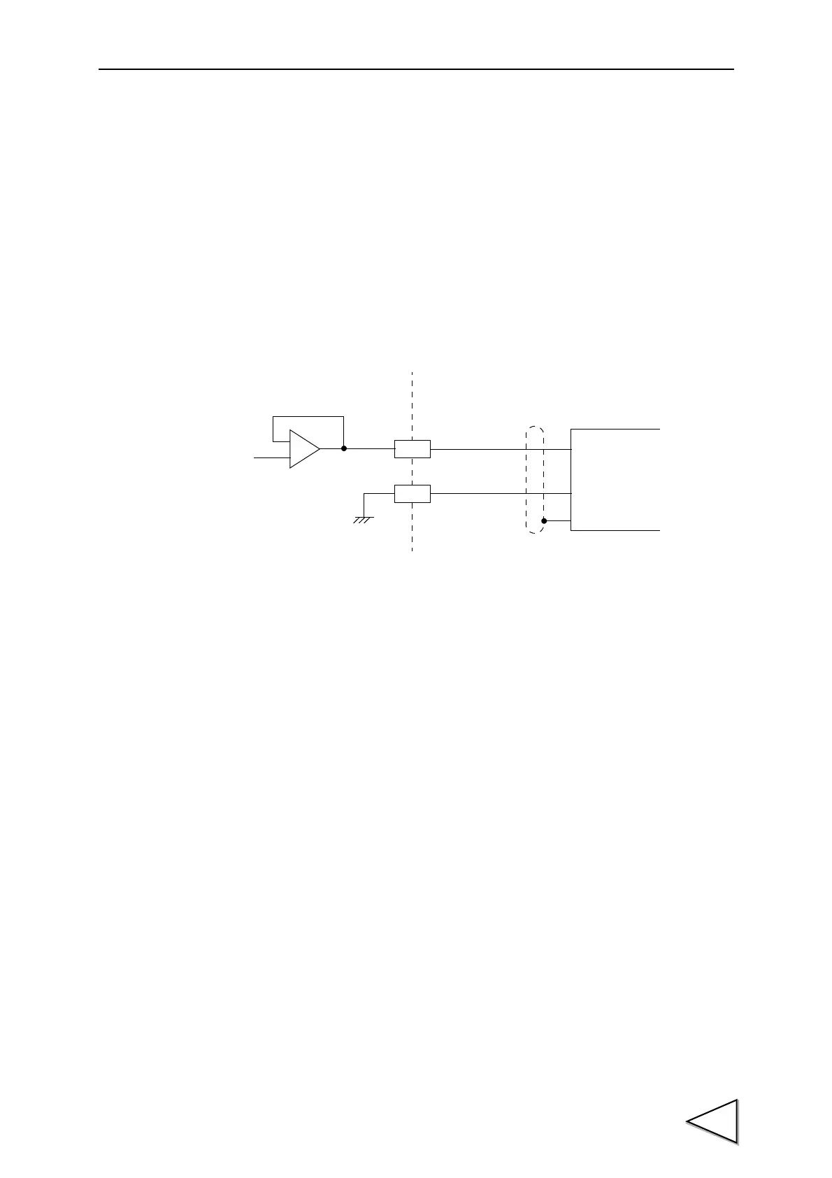
10.VOLTAGE OUTPUT(VOL OUT)
79
10. VOLTAGE OUTPUT(VOL OUT)
This interface extracts analog voltage proportional to sensor input signals. This interface
is convenient for observation and recording of waveforms with a recorder, etc.,
connected.
The output level is approx. 2V per 1mV/V of sensor input.
・ Example of output equivalent circuit and external equipment connection
Output signals are not the indicated values themselves because they are extracted before
sensor input signals are A/D-converted.
Therefore, output signals do not coincide with the digitally processed indicated values,
such as the digital zero and digital filter.
+
-
F.G
External
2
1
-
+
F371 inside
equipment