ArcLight Hub User’s Guide
Component Operating Procedures
Rev. 001 1081006 5-9
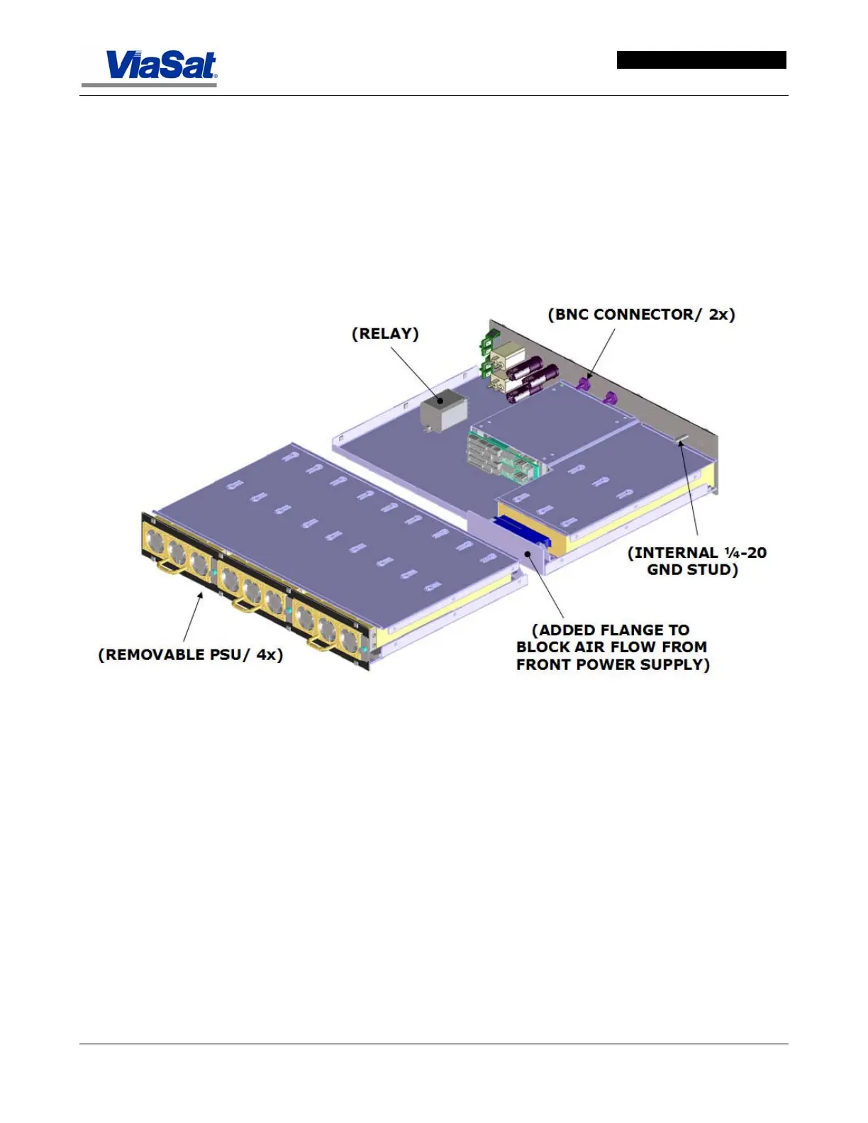
5.3.1.1 Power Supply
The ABS chassis contains 4 load sharing power supplies located below
the card cages, three in the front and one accessable at the rear of the
chassis. Only two power supplies are required for normal operation.
Each power supply senses its own output and reports a failure to the
Chassis Health Monitor (CHM). The CHM notifies the System
Controller, and the System Controller sets an SNMP trap via for the
NMS to alert the user that a supply has failed. The user can then hot-
swap the failed supply. No service interruption will result from a single
failed power supply.
Figure 5-8 shows the power supply tray.
Figure 5-8. ABS Power Supply Tray.
Figure 5-9 shows the rear panel with its fuse holders, power input
plugs, power On/Off switches, and connector inputs. Power input and
switching is for the A and B backplanes. Connectors for the IF Signal
input and 10 MHz Reference are located on this rear panel.