ArcLight Hub User’s Guide
Screen Descriptions for NMS Client
3-4 1081006 Rev. 001
scrollable hub diagram window, window resizing, and on-the-fly
addition and removal of hub components. In addition to the right-click
context menus, all configuration and status dialogs for individual
components are accessible via the main NMS Client window menu bar.
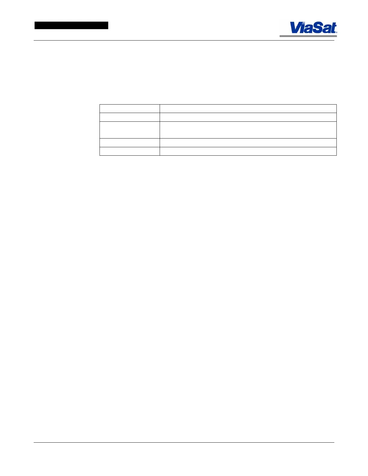
The color coding scheme used to represent component status on the
hub diagram view is defined according to the following table:
Table 3-1. Icon Color Coding Scheme.
Color Status Value
Red No connectivity to the component
Gray Network connectivity exists, but component
does not respond to SNMP polls
Yellow Outstanding component alarm
Green Component is functioning properly
Components follow a standard connection scheme regardless of type.
Hub components are automatically connected to subnets based on their
assigned IP addresses. Depending on its type, a component may
connect to multiple subnets. A hub component is defined as one of the
following: NMS, RTNMS, MCD, FLM, Hub Canceller, PEP, or APR
Server. Of these, the xPEP and APR server are not administrable
components and are included for representational purposes only. Note
that in the case of the MCD, the primary/redundant designation is
assumed to apply to the individual system processor servers. This
allows for such cases as the current single dual-system procesor
configurationm as well as two single-system procesor configuration with
one designated primary and one (with no primary IP address specified)
designated redundant.
Right-click the viewable surface to bring up the Configure Network
Components dialog via a context menu—this is the default context
menu that opens whenever a right-click action is performed outside of a
component-specific action area. In addition, the Configure Network
Components dialog is accessible via the main NMS Client window menu
bar.
The last octet, or octets, depending on subnet assignment, of hub
component network interface IP addresses is displayed next to the
components’ network connection lines on the diagram (displaying the
entire address would not be space-efficient). The number of connection
lines displayed for a component (one or two) is governed by the number
of IP addresses entered in the edit component dialog; note that the Edit
Component Dialog Screen pictured (shown in
Figure 3-4) corresponds
to the MCD component shown in the Hub Diagram Window concept
dialog. Primary and Spare components are differentiated by a “P” or “S”
next to their names.