ArcLight Hub User’s Guide
Component Operating Procedures
5-12 1081006 Rev. 001
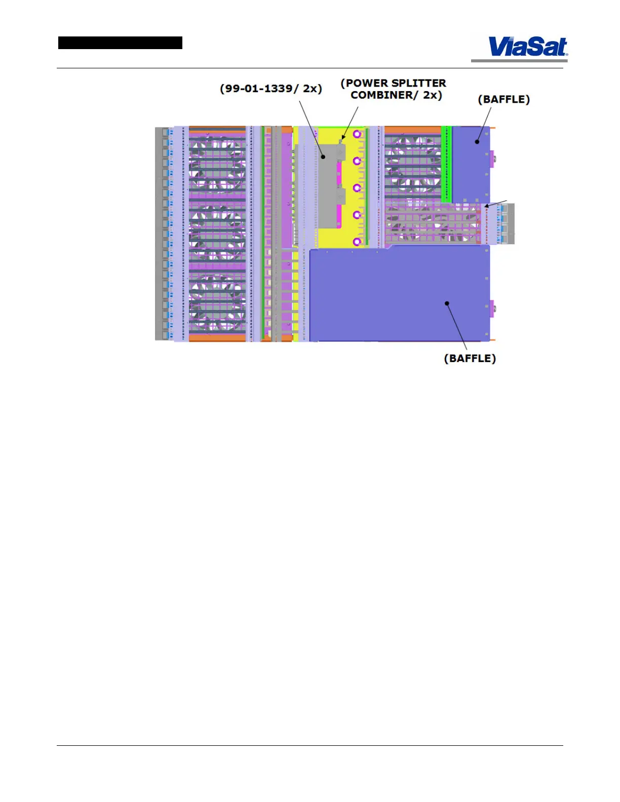
Figure 5-12. ABS Bottom Fan Tray.
Figure 5-13 illustrates the air flow generated by the fan tray of the ABS.
Perforated plates at the front and lower sides of the ABS chassis admit
cool air air and the fans move it through the chassis card cages where
it is heated. This heated air is then exhausted upwards through
perforated panels at the top sides and rear of the ABS. Care should be
taken not to obstruct the intake or exhausting of this air flow with
cables or other materials, since this would increase the temperature
withing the ABS chassis. Use the cable tray at the top of the ABS
(
Figure 5-10) for cable runs to avoid blocking air flow.