ArcLight Hub User’s Guide
General System Description
1-4 1081006 Rev. 001
• Lower cost RF equipment in the VMT – RF power
transmission equipment is governed by the required peak
transmit power and in spread spectrum systems this is
considerably lower than in non-spread systems.
System Architecture and Operation
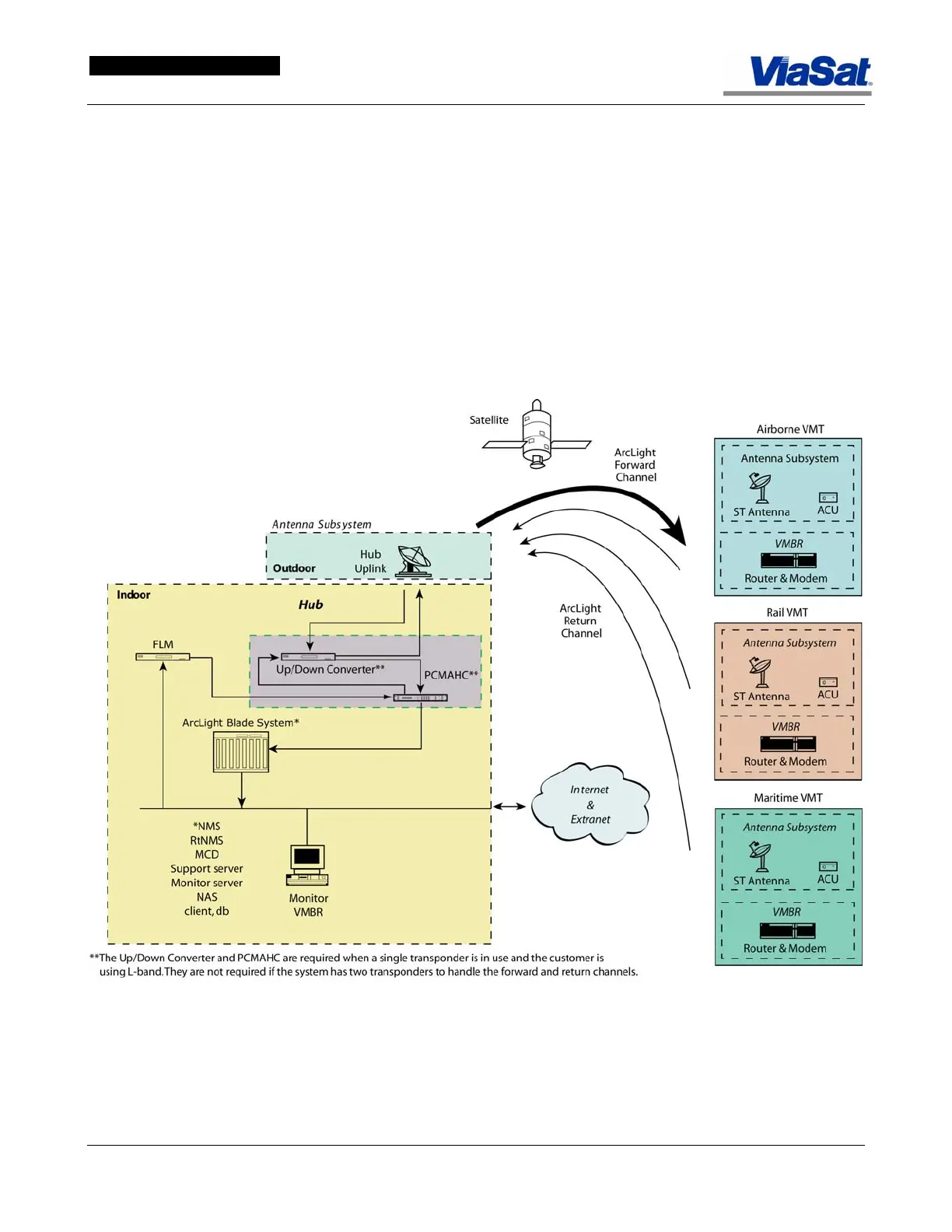
The ArcLight network topology is illustrated in Figure 1-3. An ArcLight
network consists of a single central communications node, or a Hub,
transmitting at a high rate, and many remote VMTs transmitting at
lower rates. The network is configured to provide Star network
connectivity so the VMTs always communicate with the Hub and with
each other only through the Hub.
Figure 1-3. ArcLight
TM
Network Topology
The Hub transmits (FLM) a single broadcast forward link satellite
carrier to the VMTs, cancels the forward link signal (PCMAHC), receives
and demodulates the CRMA signals from the VMTs, and provides the
terrestrial interface to the Internet and/or corporate networks. The
ArcLight Network Management System (NMS) resides at the Hub,