ArcLight Hub User’s Guide
Component Operating Procedures
Rev. 001 1081006 5-103
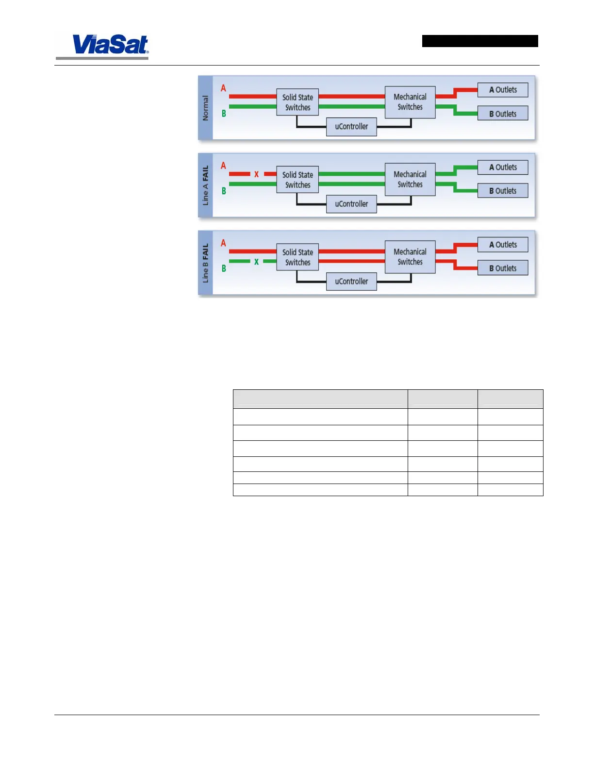
Figure 5-72. Power Transfer Process in PDU.
Table 5-22 lists the power usage of Rack 1 and Rack 2.
Table 5-22. Rack Power Usage.
Hub Racks Watts Amps
Rack 1
Circuit 1 (110VAC @ 30AMPS 3333 33.67
Circuit 2 (110VAC @ 30AMPS 3115.2 31.47
Rack 2
Circuit 3 (220VAC @ 30AMPS 6336 28.80
Circuit 4 (110VAC @ 30AMPS 418 4.22
5.27.2 PDU Installation Procedure
Refer to the ArcLight Hub Installation Guide and the Rack-Mount Fail-
Safe Transfer Switch Installation and Operations Manual available from
Server Technology for installation information.
In
Figure 5-73, Item 1 is the voltage selector switch that configures the
PDU for the installed operational voltage. It is located on the front panel
of the PDU.
Item 2 (rear panel view) identifies the power inlets that connect the PDU
to the electrical power sources.
Item 3 identifies the LEDs on the rear panel that provide power status
for the input leads.