ArcLight Hub User’s Guide
Component Operating Procedures
Rev. 001 1081006 5-11
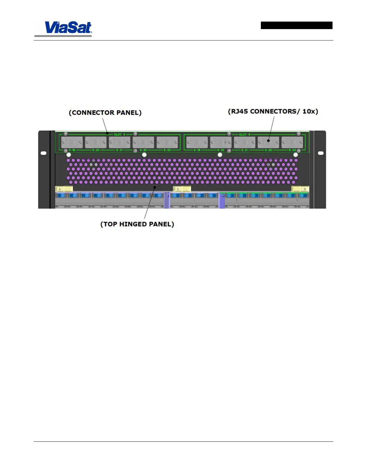
Cable access to the rear of the eleven slot backplane is provided
through a slot at the top of the card cage panel. Cables from the
RJ45 connectors at the top rear panels of the ABS should be fed
through the cable support tray before being fed into the card cage
cable access slot. The cable tray support prevents the upper
perforated panel of the card chassis from being blocked by cables,
thus ensuring adequate ventillation.
Figure 5-11. Real panel Connectors and Numbering Scheme.
The upper rear connector panel provides ten RJ45 connectors,
labeled 1 through 10. When not in use, each connector is protected
by a removable cover. This connector panel is above a large
perforated panel on hinges that drops down to allow access to the
card cages.
5.3.1.2 Fan Tray
The ABS chassis contains a fan tray located at the bottom of the
chassis (see
Figure 5-12). Each of these fans provides a ‘Fault’ output
signal to the CHM when the RPM of the fan falls below a predefined
level. This fan fault output is monitored by the CHM. Any fan failure is
relayed to the system processor. The system processor then sets a trap
for the NMS and the user is notified. The user can then hot swap the
faulty fan module.