Pinouts
TVM Series Installation and Operation Handbook 227
Copyright © 2008, Harris Corporation
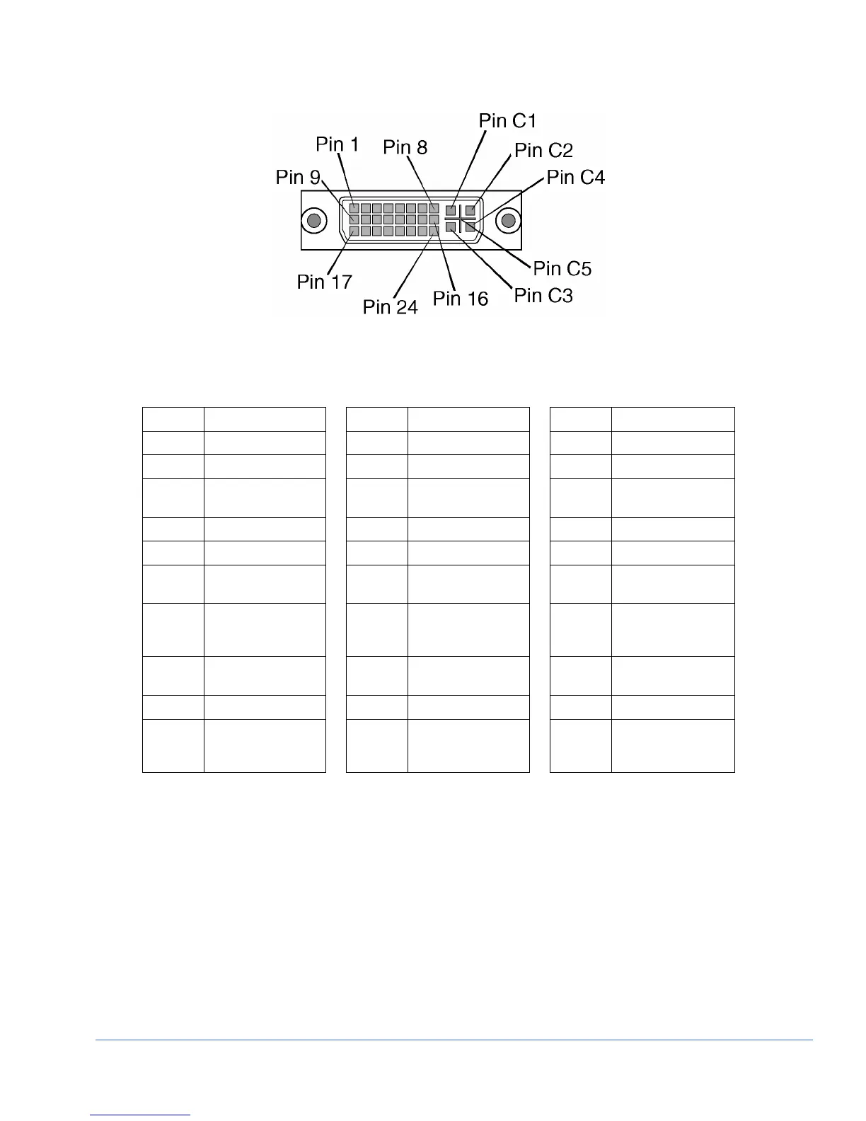
Figure B-2. DVI-I Out Connector
Table B-2. Pinouts for DVI-I Out Connector
Pinout Signal Pinout Signal Pinout Signal
1 T.M.D.S. Data 2- 9 T.M.D.S. Data 1- 17 T.M.D.S. Data 0-
2 T.M.D.S. Data 2+ 10 T.M.D.S. Data 1+ 18 T.M.D.S. Data 0+
3
T.M.D.S. Data 2/4
Shield
11
T.M.D.S. Data 1/3
Shield
19
T.M.D.S. Data 0/5
Shield
4 T.M.D.S. Data 4- 12 T.M.D.S. Data 3- 20 T.M.D.S. Data 5-
5 T.M.D.S. Data 4+ 13 T.M.D.S. Data 3+ 21 T.M.D.S. Data 5+
6
DDC Clock
14
+5V Power
22
T.M.D.S Clock
Shield
7
DDC Data
15
Ground (return for
+5V, Hsync, and
Vsync)
23
T.M.D.S. Clock+
8
Analog Vertical
Sync
16
Hot Plug Detect
24
T.M.D.S. Clock-
C1 Analog Red C2 Analog Green C3 Analog Blue
C4
Analog Horizontal
Sync
C5
Analog Ground
(analog, R, G, and
B return)
-
-