Pinouts
228 TVM Series Installation and Operation Handbook
Copyright © 2008, Harris Corporation
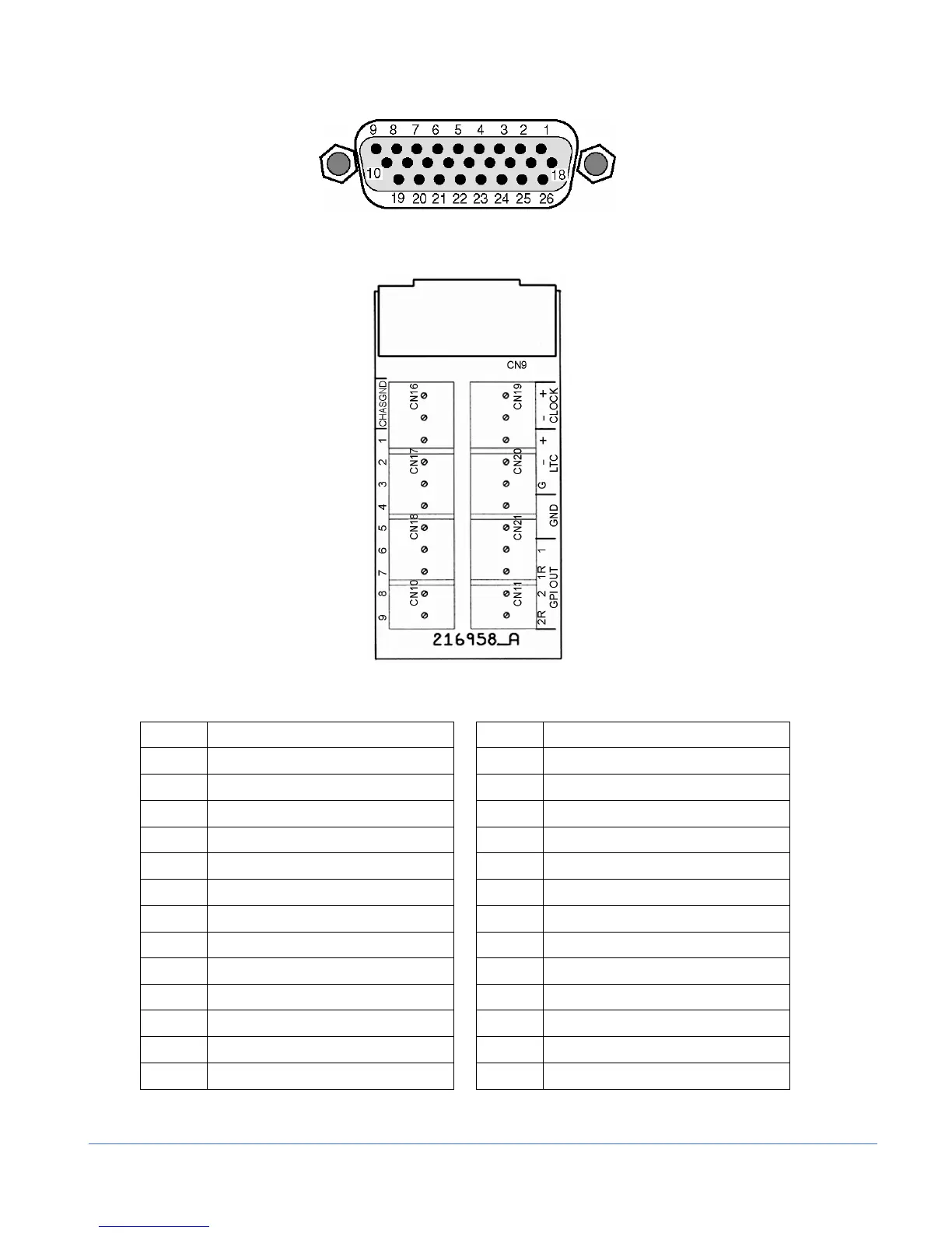
Figure B-3. LTC/GPI 26-pin, Female, D-sub Connector
Figure B-4. LTC/GPI Breakout Board
Table B-3. Pinouts for LTC/GPI Connector and LTC/GPI Breakout Board
Pinout Signal Pinout Signal
1 GND 14 Return for GPI #1
2 GPI input #4 (Select input D) 15 GPI output #2
3 GPI input #3 (Select input C) 16 Return for GPI #2
4 GPI input #2 (Select input B) 17 Reserved
5 GPI input #1 (Select input A) 18 Reserved
6 GPI input #7 (Select Preset 3) 19 Clock high in
7 GPI input #8 (Select Preset 4) 20 Clock low in
8 GPI input #9 (Select Preset 5) 21 Reserved
9 GPI input #6 (Select Preset 2) 22 Reserved
10 GPI input #5 (Select Preset 1) 23 Reserved
11 GND 24 LTC high in
12 Reserved 25 LTC ground
13 GPI output #1 26 LTC low in