Pinouts
TVM Series Installation and Operation Handbook 229
Copyright © 2008, Harris Corporation
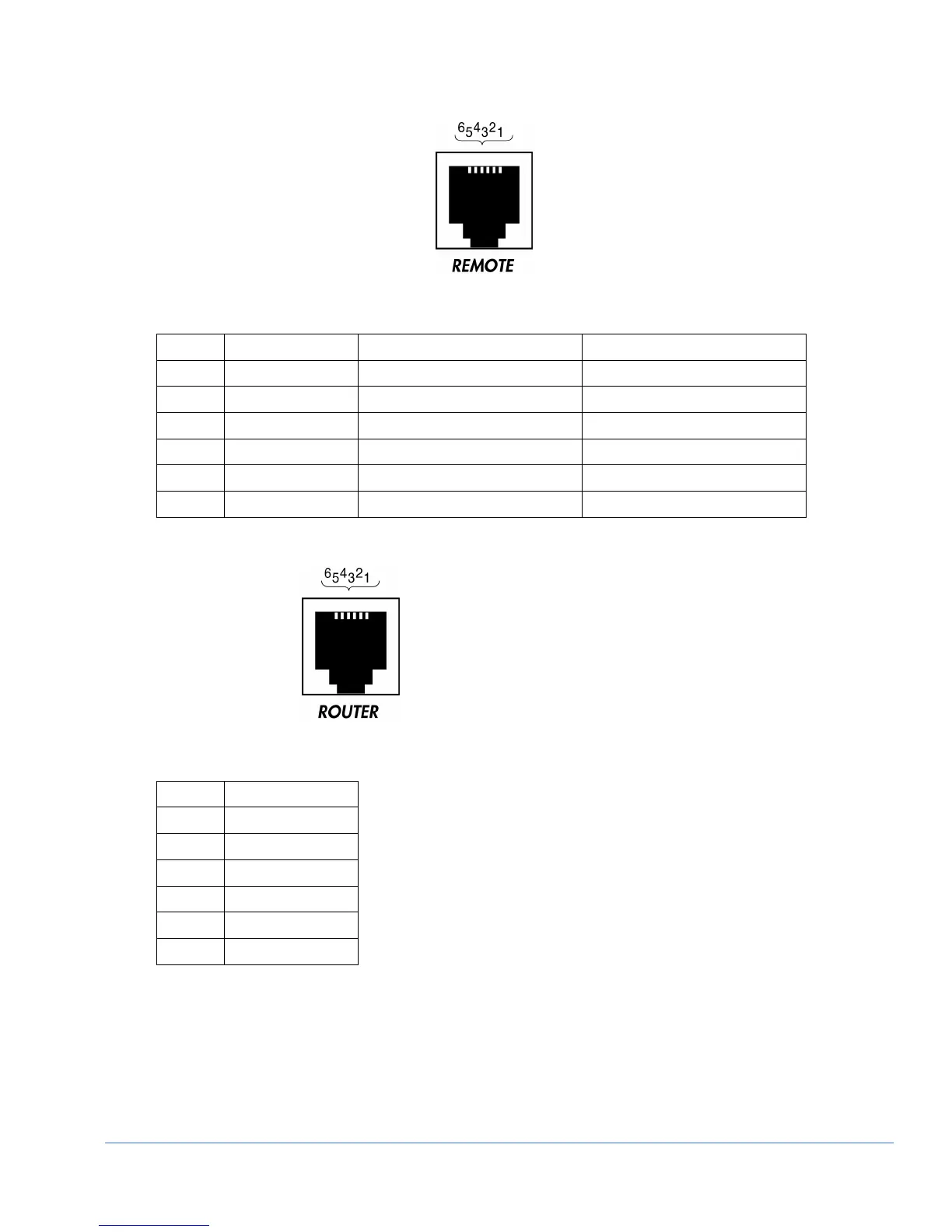
Figure B-5. Remote RJ-11 Control Connector
Table B-4. Remote RJ-11 Control Connector Pinouts
Pinout Signal TVM RCU1000
1 OPEN Open GND
2 RX - Received by TVM Series Transmit from RCU
3 RX + Received by TVM Series Transmit from RCU
4 TX - Transmit from TVM Series Received by RCU
5 TX + Transmit from TVM Series Received by RCU
6 GND GND GND
Figure B-6. Router RJ-11 Control Connector
Table B-5. Router RJ-11 Control Connector Pinouts
Pinout Signal
1 OPEN
2 OPEN
3 TX
4 RX
5 OPEN
6 GND