22 Device Description WAGO I/O System 750 XTR
750-677/040-000 4PWM 24 VDC 0.2A XTR
Manual
Version 1.0.0
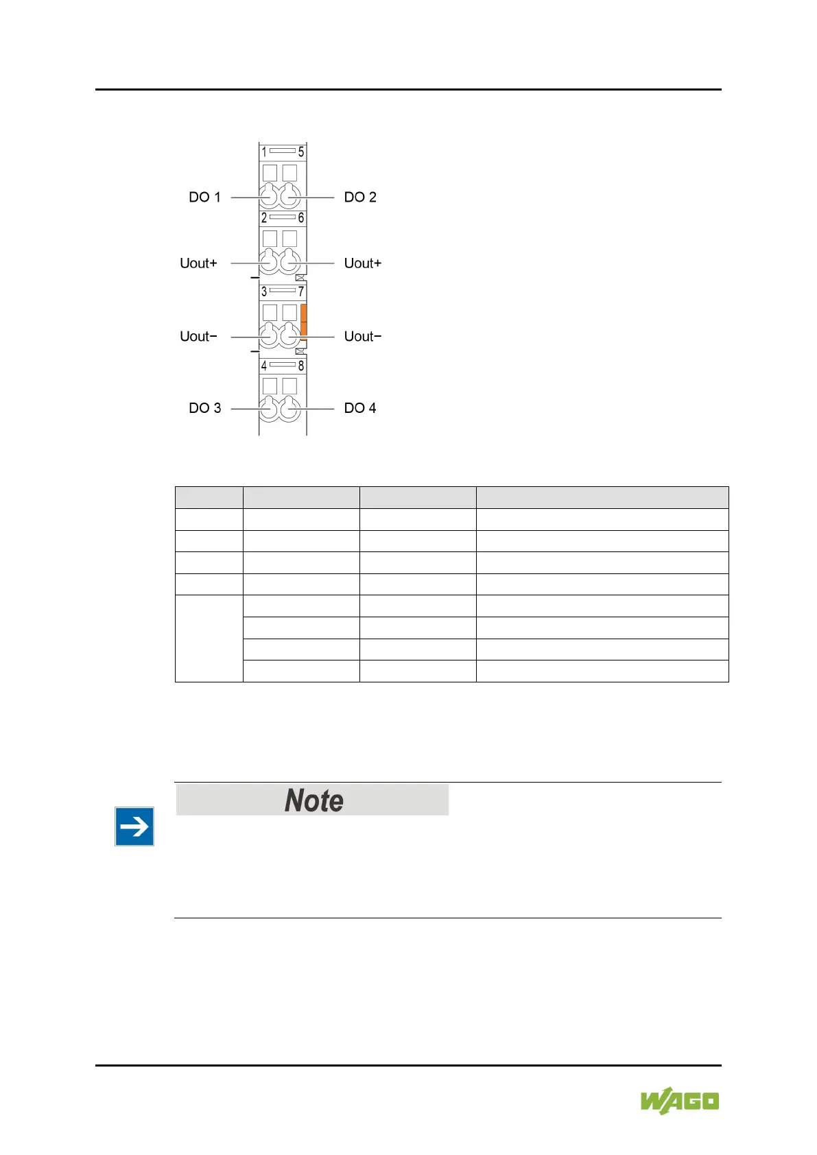
3.2.3 CAGE CLAMP
®
Connectors
Figure 4: CAGE CLAMP
®
Connectors
Table 5: Legend for Figure “CAGE CLAMP
®
Connectors”
-
Reference potential LSS
*)
Reference potential HSS
**)
Reference potential LSS
*)
Reference potential HSS
**)
for negative switching configured output (inverted output)
**)
for positive switching configured output (non-inverted outpu)
Use shielded signal lines!
Only use shielded signal lines for analog signals and I/O modules which are
equipped with shield clamps. Only then can you ensure that the accuracy and
interference immunity specified for the respective I/O module can be achieved
even in the presence of interference acting on the signal cable.

 Loading...


