WAGO I/O System 750 XTR Operating Modes 53
750-677/040-000 4PWM 24 VDC 0.2A XTR
Manual
Version 1.0.0
4.3.3 Function of the Output Channels
Output 1 (DO 1): Output signal
Output 2 (DO 2): Count direction
*)
Output 3 (DO 3): Output signal
Output 4 (DO 4): Count direction
*)
*)
L = negative: −1 … −20,000 Hz or 0xB1E0 to 0xFFFF,
H = positive: 1 … 20,000 Hz or 0x0001 to 0x4E20
4.3.4 Process Values (PWM Frq-Cnt)
The frequency is specified in [Hz] via the process output data.
1 digit equals 1 Hz.
Valid value ranges for the process image:
• Positive value range: 0x0001 … 0x4E20 (1 Hz … 20000 Hz)
• Negative value range: 0xB1E0 … 0xFFFF (
−20000 Hz … −1 Hz)
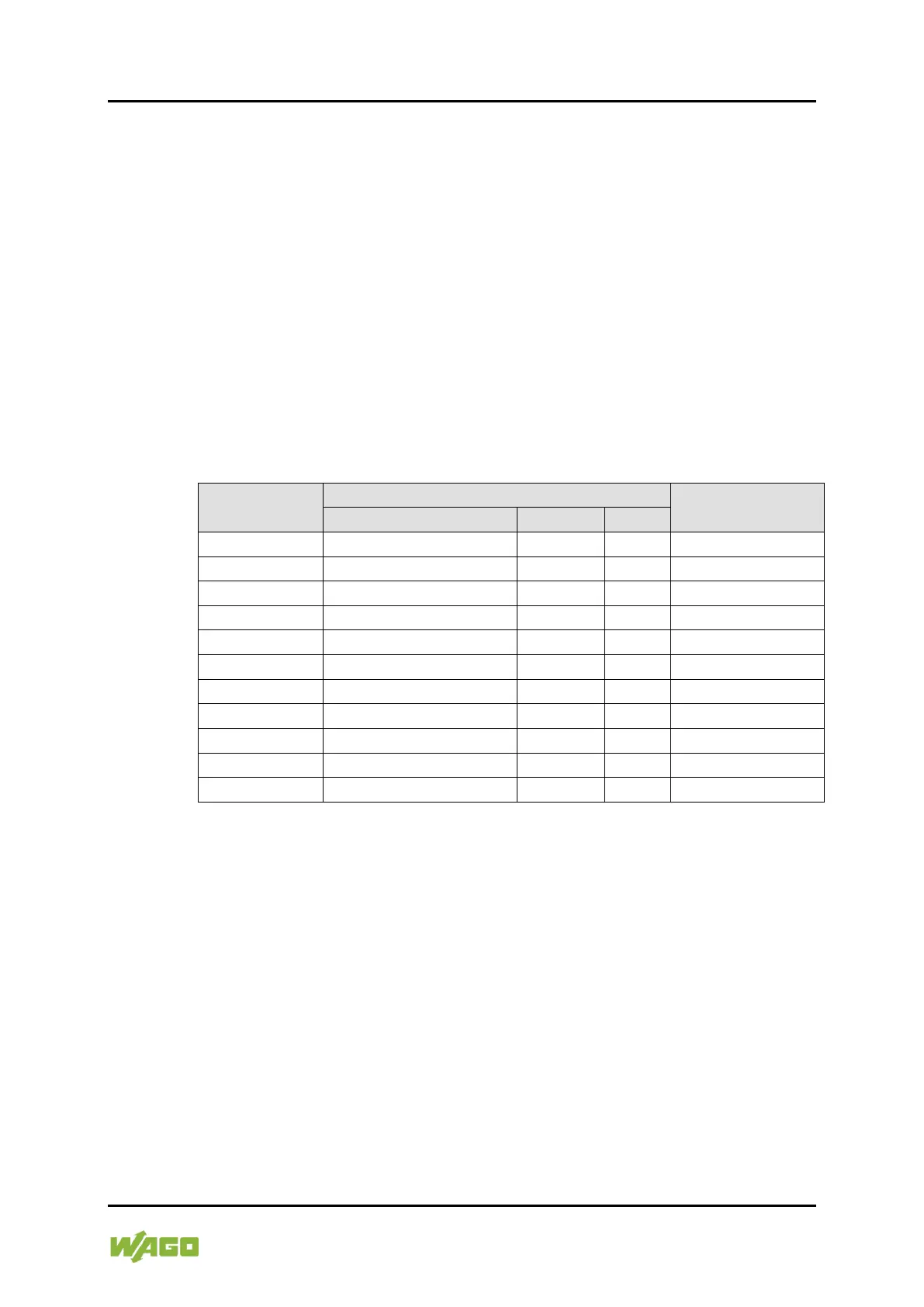
Table 40: Process Values (PWM Frq-Cnt)
[Hz]
DO 2 or DO 4
*)
If the process value = 0, the previous level of the direction output is retained.

 Loading...


