54 Operating Modes WAGO I/O System 750 XTR
750-677/040-000 4PWM 24 VDC 0.2A XTR
Manual
Version 1.0.0
4.4 Pulse Frq-Cnt
In this operating mode, the frequency can vary from 0… 20 kHz via the process
image. The PWM cycles that have already been output are counted via the input
process image. The pulse duration can be preset from the parameterization
dialog. The default value is “50 µs”.
Of the 4 channels, two each are corresponding. The first output (DO 1 or DO 3)
outputs the PWM signal and the second (DO 2 or DO 4) the count direction.
The PWM output is started at the rising edge of control bit 1.
To stop, a falling edge must occur at control bit 1.
When the PWM output is restarted, the counting process is continued from the
stopped value.
The frequency of the signal can be changed during the PWM output. An enabled
PWM output is signaled by status bit 1.
The count value can be reset by a rising edge at control bit 2.
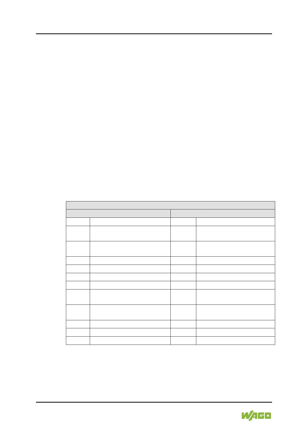
4.4.1 Process Image
Table 41: Process Image (Pulse Frq-Cnt)
D0
DO 1 count PWM cycles low
byte
D0 DO1 Frequency low byte
D1
DO 1 count PWM cycles high
byte
D1 DO1 Frequency high byte
D4
DO 3 count PWM cycles low
byte
D4 DO3 Frequency low byte
D5
DO 3 count PWM cycles high
byte
D5 DO3 Frequency high byte

 Loading...


