WAGO I/O System 750 XTR Commissioning 85
750-677/040-000 4PWM 24 VDC 0.2A XTR
Manual
Version 1.0.0
Example 4:
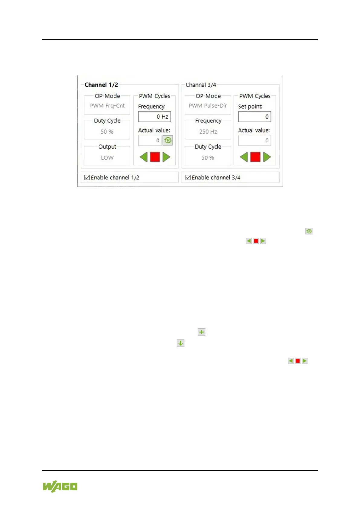
Channel 1/2: PWM Frq-Cnt
Channel 3/4: PWM Pulse-Dir
Figure 33: Data Dialog, Example 4
The complex operating mode “PWM Frq-Cnt” is preset for Channel 1/2.
The function results from the interaction of both channels and is therefore
combined. The process data value (frequency) can be entered as a value. The
counter (actual value) is displayed and can be reset with the adjacent button ( ).
The counting direction is set by pressing the arrow keys ( ).
Channel pair 1/2 is enabled (checkbox selected), the associated output is
therefore not high-impedance.
The complex operating mode “PWM Pulse-Dir” is preset for Channel 3/4.
The function results from the interaction of both channels and is therefore
combined. The process data value (number of PWM cycles) can be entered as a
setpoint.
The counter (residual value) is displayed and can be:
• Increased by the entered setpoint ( button) or
• Set to the entered setpoint ( button).
The counting process is started by pressing one of the two arrow keys ( ).
In both cases, the count is decreased.
• The right arrow key also sets the corresponding output DO 4 in the control
byte to “High”.
• The left arrow key also sets the corresponding output DO 4 to “Low”.
• The Stop button is used to stop the counting process.
Channel pair 3/4 is enabled (checkbox selected), the associated output is
therefore not high-impedance.

 Loading...


