EasyManuals Logo

WAGO 750 XTR User Manual

WAGO 750 XTR
108 pages
To Next Page IconTo Next Page
To Previous Page IconTo Previous Page
Page #87 background imageLoading...
Page #87 background image
WAGO I/O System 750 XTR Commissioning 87
750-677/040-000 4PWM 24 VDC 0.2A XTR
Manual
Version 1.0.0
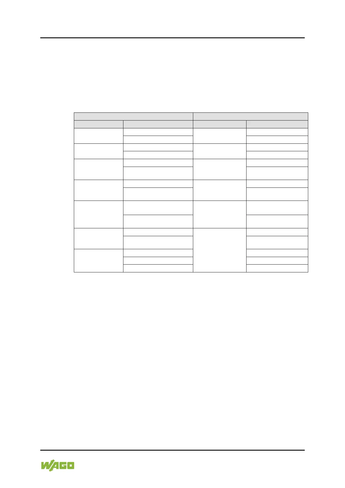
The 750-333/040-000 fieldbus couplers allow channel pair granular
parameterization of the diagnostics as well as further module and channel or
channel pair specific settings. The following assignment applies to the
parameters of the I/O module, also in connection with the use of WAGO-I/O-
CHECK or e!COCKPIT.
Table 60: Device-Specific Parameters
GSD File
WAGO-I/O-CHECK and e!COCKPIT
Description
Value
Selection Box
Value
I/O-module is
physically
plugged
*)
-
-
(optional) not plug fitted
-
Watchdog timer
[I/O module]
deactivated
Watchdog timer
[General]
Checkbox disabled
activated
*)
Checkbox enabled
*)
Diagnosis
[Channel pair x
(x = 0,1)]
disabled
*)
-
-
enabled
-
Bridge mode
[Channel pair x
(x = 1, 2)]
deactivated
*)
Bridge mode
[Channel x
(x = 1 & 2, 3 & 4)]
Checkbox disabled
*)
activated
Checkbox enabled
Load between
output and
[Channel x
(x = 0, 1, 2, 3)]
Uout to CC 2 or CC6
*)
Load between output
and
[Channel x
(x = 1 & 2, 3 & 4)]
Uout
*)
Uout+ to CC 3 or CC7
Uout+
Operating mode
[Channel x
(x = 0, 1, 2, 3)]
PWM DC
*)
Operating mode
[Channel x
(x = 1 & 2, 3 & 4)]
PWM DC
PWM Frq
PWM Frq
Operating mode
[Channel x
(x = 0, 2)]
PWM Frq-Cnt
PWM Frq-Cnt
Pulse Frq-Cnt
Pulse Frq-Cnt
PWM Pulse-Dir
PWM Pulse-Dir
*)
Factory default

Table of Contents

Questions and Answers:

Question and Answer IconNeed help?

Do you have a question about the WAGO 750 XTR and is the answer not in the manual?

WAGO 750 XTR Specifications

General IconGeneral
BrandWAGO
Model750 XTR
CategoryI/O Systems
LanguageEnglish

Related product manuals