44 Operating Modes WAGO I/O System 750 XTR
750-677/040-000 4PWM 24 VDC 0.2A XTR
Manual
Version 1.0.0
4.1.1 Process Image
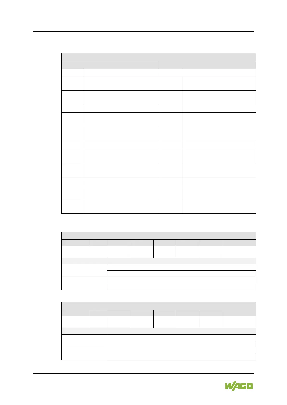
Table 23: Process Image (PWM DC)
D0 - D0
DO 1 Pulse-pause ratio
low byte
D1 - D1
DO 1 Pulse-pause ratio
high byte
D2 - D2
DO 2 Pulse-pause ratio
low byte
D3 - D3
DO 2 Pulse-pause ratio
high byte
D4 - D4
DO 3 Pulse-pause ratio
low byte
D5 - D5
DO 3 Pulse-pause ratio
high byte
D6 - D6
DO 4 Pulse-pause ratio
low byte
D7 - D7
DO 4 Pulse-pause ratio
high byte
Table 24: Control Byte 0 (PWM DC)
RegCom - - - - - -
Enable DO 1 &
DO 2 Drivers
DO 2 Drivers
0: The output driver for DO 1 & DO 2 is disabled.
1: The output driver for DO 1 & DO 2 is enabled.
RegCom
0: Register communication is switched off.
1: Register communication is switched on.
Table 25: Control Byte 2 (PWM DC)
RegCom - - - - - -
Enable DO 3 &
DO 4 Drivers
DO 4 Drivers
0: The output driver for DO 3 & DO 4 is disabled.
1: The output driver for DO 3 & DO 4 is enabled.
RegCom
0: Register communication is switched off.
1: Register communication is switched on.

 Loading...


