WAGO I/O System 750 XTR Diagnostics 89
750-677/040-000 4PWM 24 VDC 0.2A XTR
Manual
Version 1.0.0
9.3 Diagnostics via Indicators
The indicators of the I/O module provide information about possible states and
cases of error. The tables below contain the interpretations of the signals.
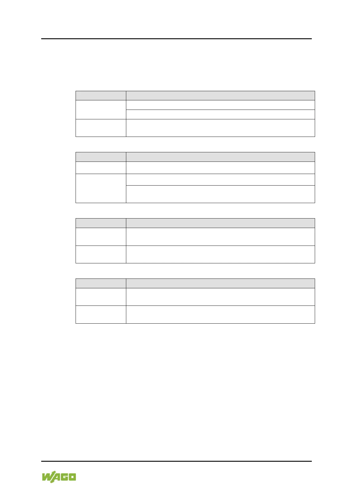
Table 64: Signal Evaluation – Status LED “A”
Off
Local bus communication absent or interrupted
Green
Operational readiness and uninterrupted local bus
communication
Table 65: Signal Evaluation – Error LED “E”
Off No malfunction
Red
Short circuit of an output to "Uout+" or "Uout-".
Undervoltage (e.g. missing field supply or as a result of
overload)
Table 66: Signal Evaluation – Channel LED “C”
Off
Channel 1 + 2 are not enabled
(the drivers for the outputs DO 1 & DO 2 are not enabled)
Green
Channel 1 + 2 are enabled
(the drivers for the outputs DO 1 & DO 2 are enabled)
Table 67: Signal Evaluation – Channel LED “G”
Off
Channel 3 + 4 are not enabled
(the drivers for the outputs DO 3 & DO 4 are not enabled)
Green
Channel 3 + 4 are enabled
(the drivers for the outputs DO 3 & DO 4 are enabled)

 Loading...


