60 Operating Modes WAGO I/O System 750 XTR
750-677/040-000 4PWM 24 VDC 0.2A XTR
Manual
Version 1.0.0
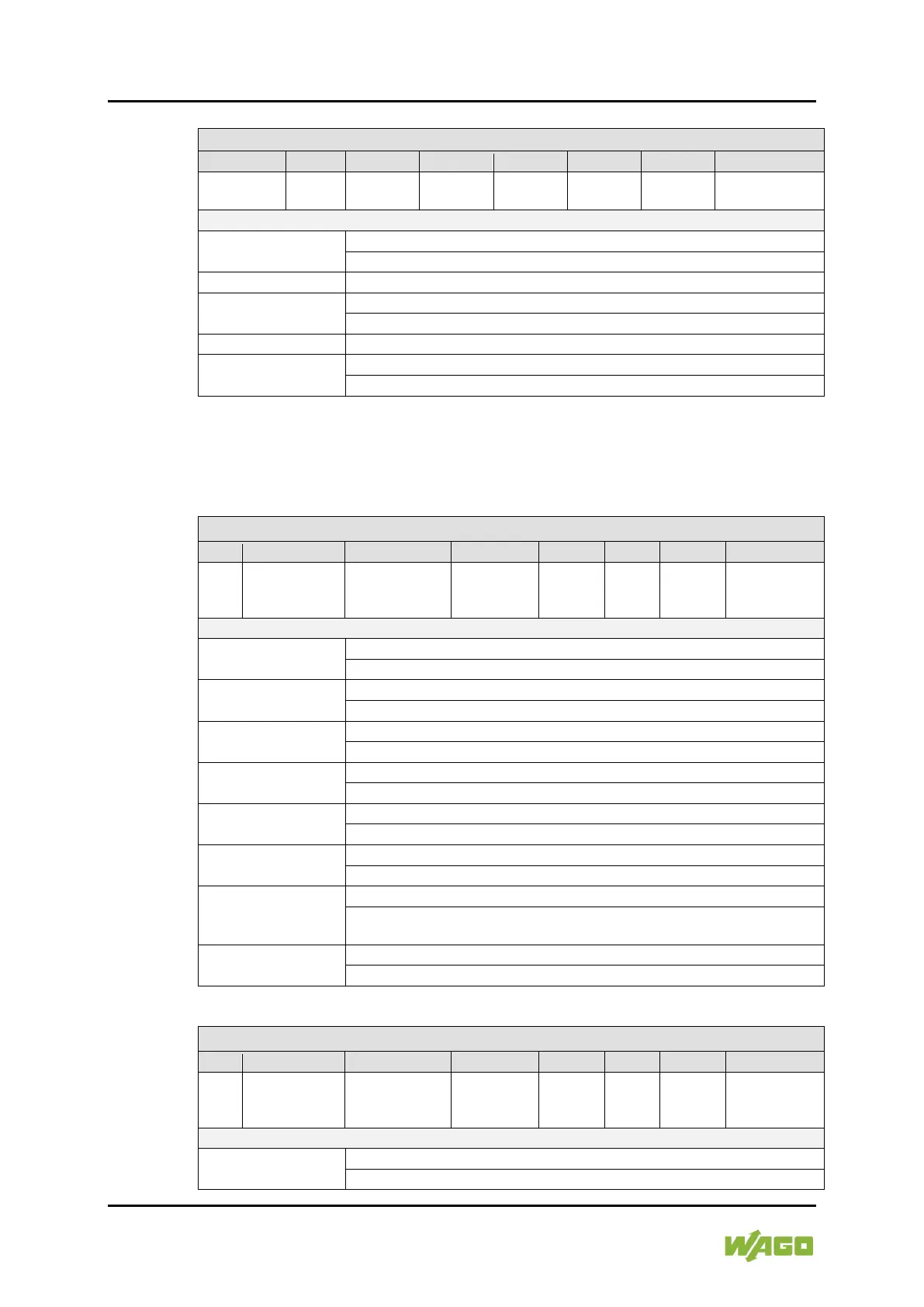
Table 49: Control Byte 2 (PWM Pulse-Dir)
RegCom - -
Enable DO 3 &
DO 4 Drivers
Start/stop PWM
Negative edge: The PWM output at DO 3 is stopped.
Positive edge: The PWM output at DO 3 is started.
Positive edge: The residual value is set to the current setpoint.
Set output DO 4
0: The output DO4 is disabled.
1: The output DO4 is enabled.
Positive edge: Adds the setpoint to the current residual value.
RegCom
0: Register communication is switched off.
1: Register communication is switched on.
Control bytes 1 and 3 can be permanently “0” and have no influence on the
system.
Table 50: Status Byte 0 (PWM Pulse-Dir)
Reg
Com
General Error
Bit
Undervoltage
DO 1 or
output
PWM
started
PWM
enabled
DO 1 & DO 2
Drivers
0: The status of the output driver for DO 1 & DO 2 is disabled.
1: The status of the output driver for DO 1 & DO 2 is enabled.
PWM enabled
0: No output of a PWM signal is enabled.
1: The PWM output is enabled.
PWM started
0: The output of the PWM signal has not yet started.
1: The output of the PWM signal has started.
Status of output DO 2
0: The output DO 2 is disabled.
1: The output DO 2 is enabled.
DO 2
0: There is no short circuit at outputs DO 1 or DO 2.
1: There is a short circuit at output DO 1 or DO 2.
Undervoltage
0: There is no undervoltage on the I/O module.
1: There is an undervoltage on the I/O module.
General Error Bit
1: There is an undervoltage or a short circuit.
Bits 0-3 are masked out.
RegCom
0: Register communication is disabled (normal mode).
1: Register communication is enabled.
Table 51: Status Byte 2 (PWM Pulse-Dir)
Reg
Com
General Error
Bit
Undervoltage
DO 3 or
output
PWM
started
PWM
enabled
DO 3 & DO 4
Drivers
0: The status of the output driver for DO 3 & DO 4 is disabled.
1: The status of the output driver for DO 3 & DO 4 is enabled.

 Loading...


