WAGO I/O System 750 XTR Device Description 39
750-677/040-000 4PWM 24 VDC 0.2A XTR
Manual
Version 1.0.0
3.7.1 Notes and Limitations on Areas of Application
3.7.1.1 Power plants and voltage substations
When used in power plants and in high/medium voltage substations, the cables
to the actuators must be shielded from a length of 10 m upwards.
For the complex operating modes (PWM Frq-Cnt, Pulse Frq-Cnt and PWM
Pulse-Dir), the cables to the actuators must be shielded from a length of 2 m.
For the complex operating modes, an additional cable length restriction of the
field supply to 2 m applies for unshielded cables.
When using shielded cables, this additional restriction does not apply.
3.7.1.2 Residential Applications
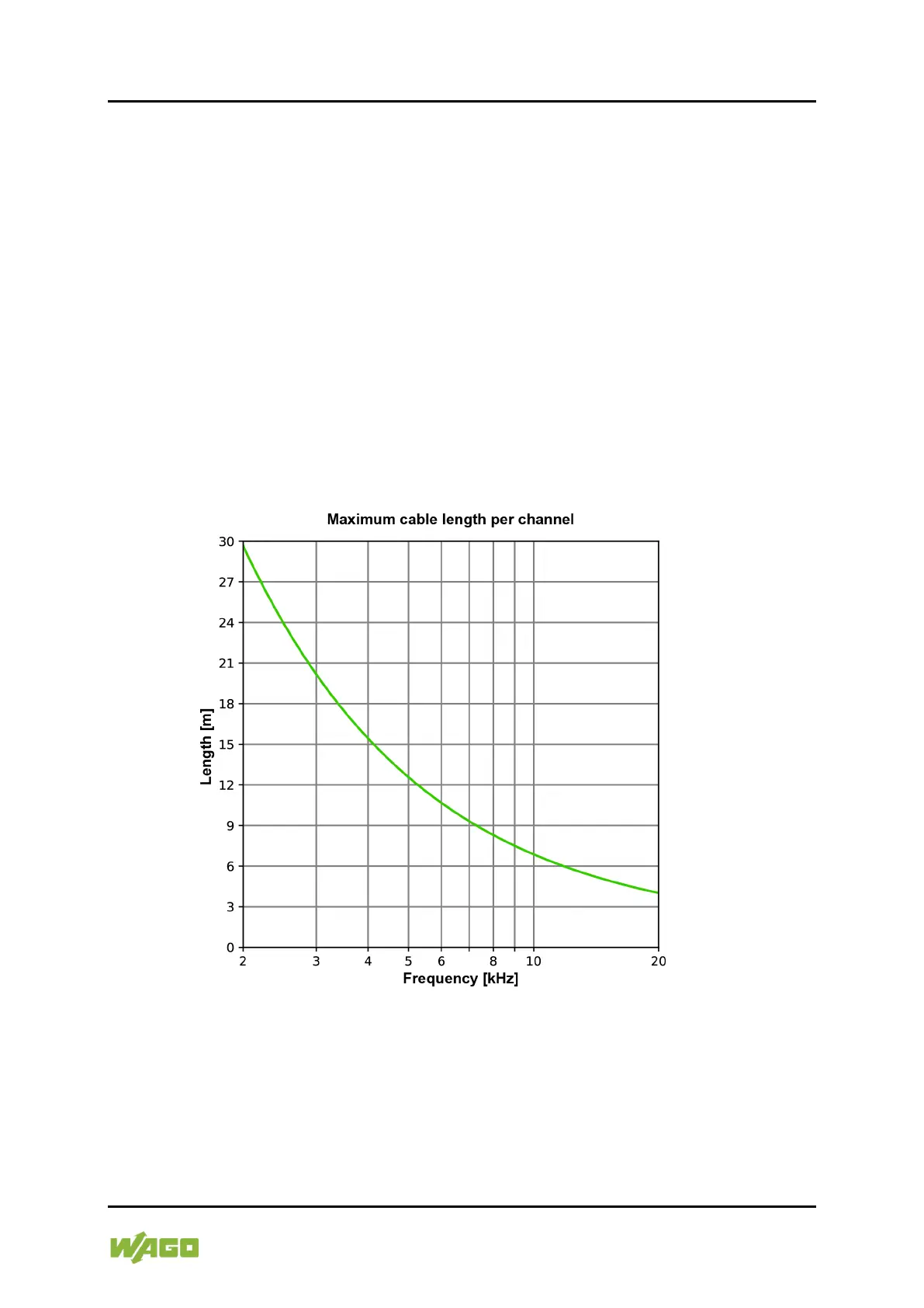
When used in residential buildings according to EN 61000-6-3, a maximum
permissible cable length applies (cable capacitance wire to shield of max. 170
pF/m) depending on the frequency:
Figure 7: Diagram for Determining the Cable Length in Residential Applications
The cable length shown in the diagram applies per channel when all channels
are occupied.
The total length of the connected cables of all channels is critical. If fewer
channels are used or individual channels are provided with shorter cables, the
remaining cable lengths can be made longer.

 Loading...


