68 Connect Devices WAGO I/O System 750 XTR
750-677/040-000 4PWM 24 VDC 0.2A XTR
Manual
Version 1.0.0
7.2 Connection Examples
Use shielded signal lines!
Only use shielded signal lines for analog signals and I/O modules which are
equipped with shield clamps. Only then can you ensure that the accuracy and
interference immunity specified for the respective I/O module can be achieved
even in the presence of interference acting on the signal cable.
Reference potential for loads
The terminals Uout- or Uout+ (see connection examples) must be used as
reference potential for the loads, as otherwise internal protection and filter
functions are disabled.
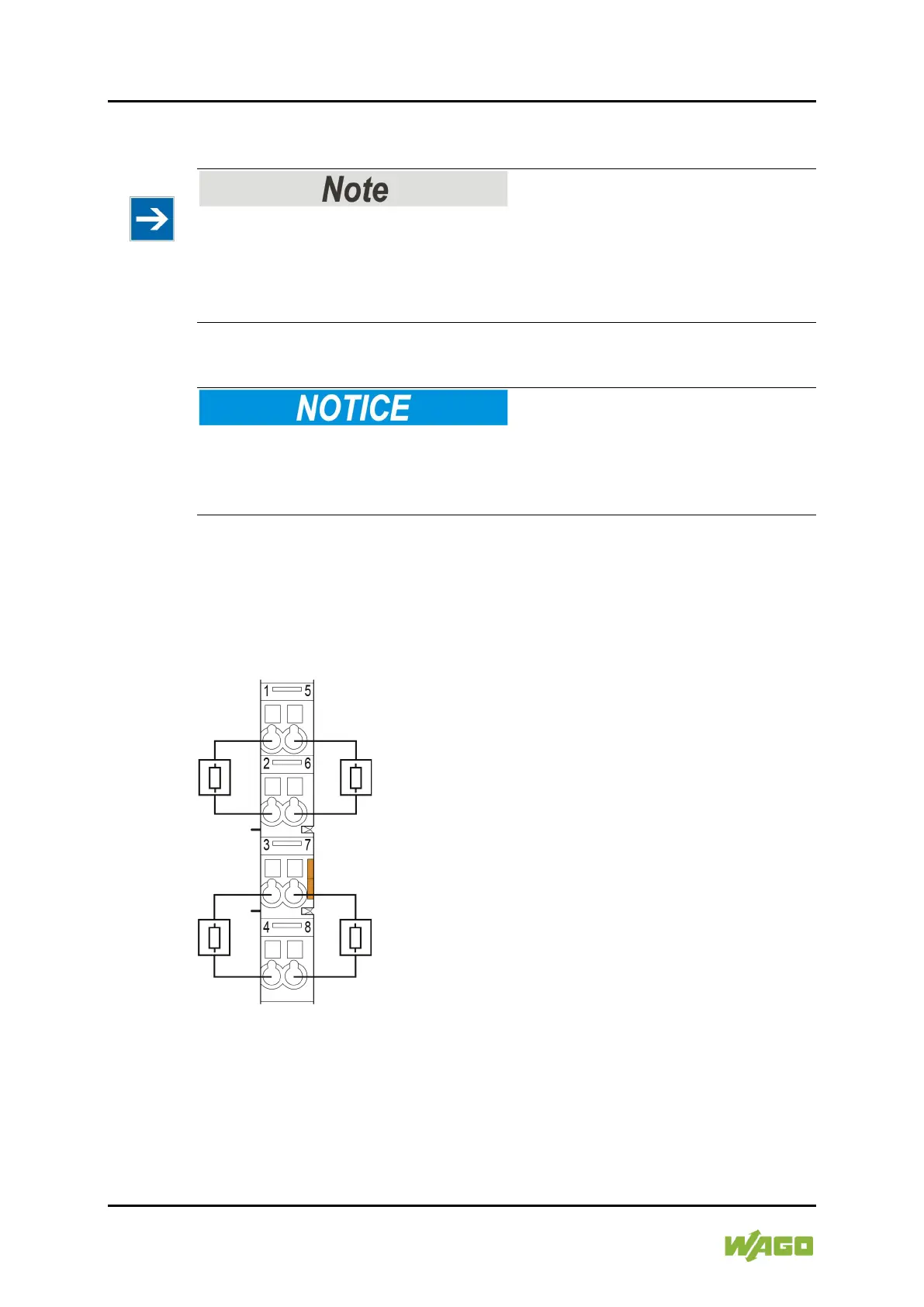
Example 1: 2 channels are configured with inverted output ("load between output
and Uout+"), 2 channels are configured with non-inverted output ("load between
output and Uout−"). The loads are connected accordingly against Uout+,
respectively against Uout−.
Figure 13: Connection Example 1

 Loading...


