WAGO I/O System 750 XTR Commissioning 83
750-677/040-000 4PWM 24 VDC 0.2A XTR
Manual
Version 1.0.0
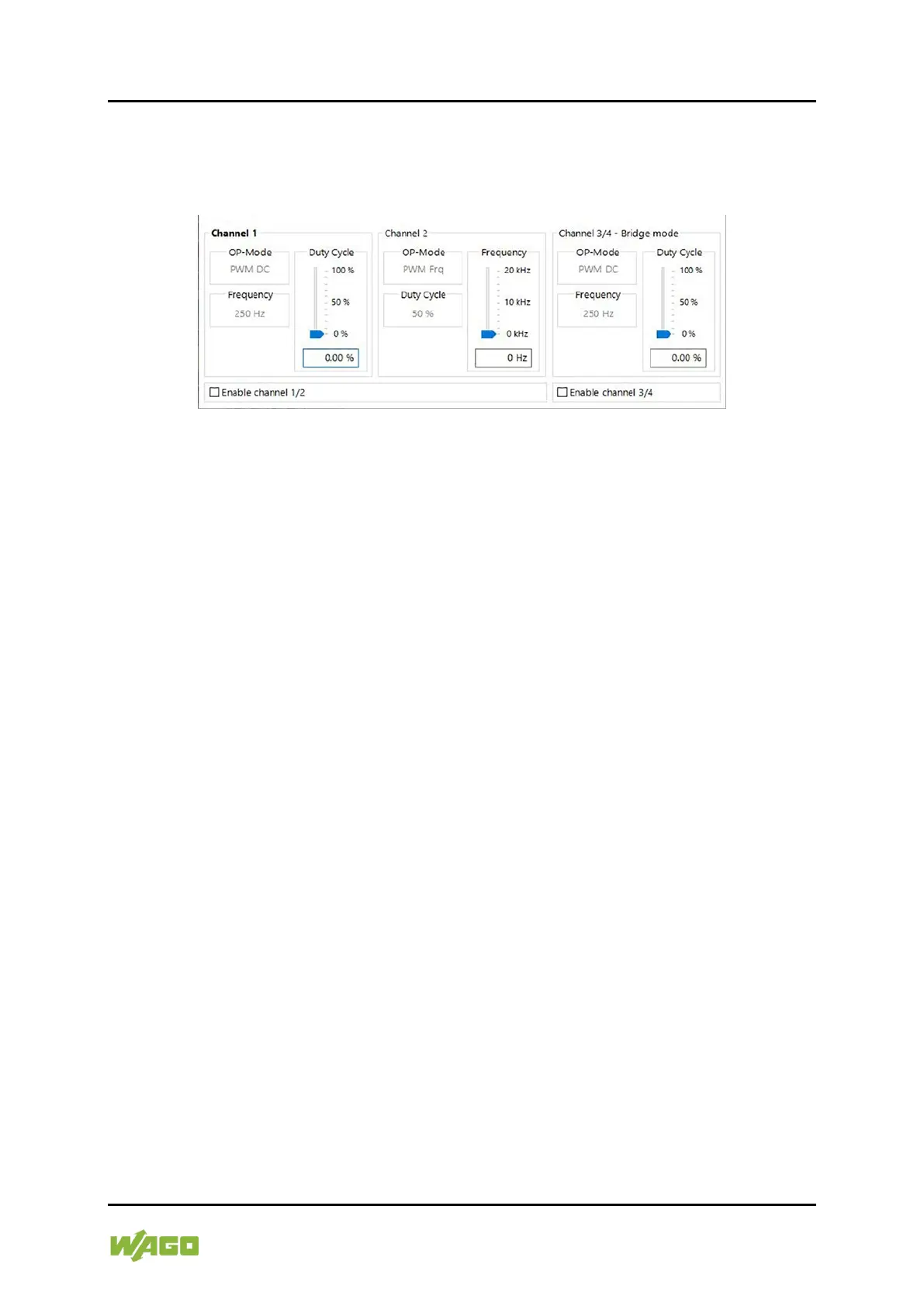
Example 2:
Channel 1: PWM DC
Channel 2: PWM Frq
Channel 3/4: PWM DC, bridge mode
Figure 30: Data Dialog, Example 2
The Channel 1 area shows the controls for the preset PWM DC operating mode.
The process data value (duty cycle) can be entered as a value or set with the
slider and changed dynamically.
The Channel 2 area shows the controls for the preset PWM Frq operating mode.
The process data value (frequency) can be entered as a value or set with the
slider and changed dynamically.
The bridge mode is preset for Channel 3/4, so only one common display area
appears for this channel pair.
The preset operating mode is PWM DC at a frequency of 250 Hz.
The process data value (duty cycle) can be entered as a value or set with the
slider and changed dynamically.
None of the channel pairs is enabled, the outputs are therefore high-resistance
(Tri-State).

 Loading...


