52 Operating Modes WAGO I/O System 750 XTR
750-677/040-000 4PWM 24 VDC 0.2A XTR
Manual
Version 1.0.0
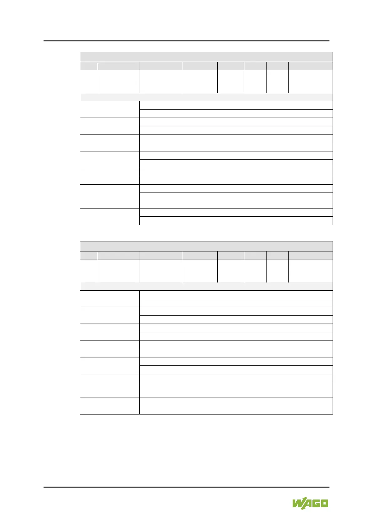
Table 38: Status Byte 0 (PWM Frq-Cnt)
Reg
Com
General Error
Bit
Undervoltage
DO 1 or
output
-
enable
Enable DO 1 &
DO 2 Drivers
Drivers
0: The status of the output driver for DO 1 & DO 2 is disabled.
1: The status of the output driver for DO 1 and DO 2 is enabled.
PWM enabled
0: No output of a PWM signal is enabled.
1: The PWM output is enabled.
Status of output DO 2
0: The output DO 2 is disabled.
1: The output DO 2 is enabled.
DO 2
0: There is no short circuit at outputs DO 1 or DO 2.
1: There is a short circuit at output DO 1 or DO 2.
Undervoltage
0: There is no undervoltage on the I/O module.
1: There is an undervoltage on the I/O module.
General Error Bit
1: There is an undervoltage or a short circuit.
Bits 0-3 are masked out.
RegCom
0: Register communication is disabled (normal mode).
1: Register communication is enabled.
Table 39: Status Byte 2 (PWM Frq-Cnt)
Reg
Com
General Error
Bit
Undervoltage
DO 3 or
output
-
enable
Enable DO 3 &
DO 4 Drivers
Drivers
0: The status of the output driver for DO 3 & DO 4 is disabled.
1: The status of the output driver for DO 3 & DO 4 is enabled.
PWM enabled
0: No output of a PWM signal is enabled.
1: The PWM output is enabled.
Status of output DO 4
0: The output DO 4 is disabled.
1: The output DO 4 is enabled.
DO 4
0: There is no short circuit at outputs DO 3 or DO 4.
1: There is a short circuit at output DO 3 or DO 4.
Undervoltage
0: There is no undervoltage on the I/O module.
1: There is an undervoltage on the I/O module.
General Error Bit
1: There is an undervoltage or a short circuit.
Bits 0-3 are masked out.
RegCom
0: Register communication is disabled (normal mode).
1: Register communication is enabled.
Status byte 1 and 3 are permanently “0”.
4.3.2 Parameter Settings
The duty cycle can be preset in a range of 0 … 100 %.
When switching on for the first time, the default value of 50 % is loaded for this
parameter.

 Loading...


