66 Mounting WAGO I/O System 750 XTR
750-677/040-000 4PWM 24 VDC 0.2A XTR
Manual
Version 1.0.0
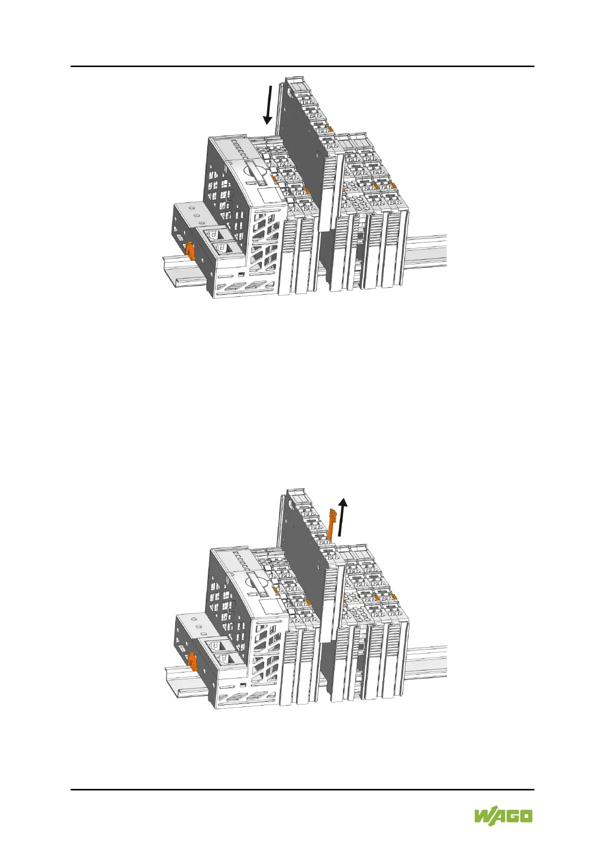
Figure 10: Snap the I/O Module into Place (Example)
3. Check that the I/O module is seated securely on the carrier rail and in the
assembly. The I/O module must not be inserted crooked or askew.
Once the I/O module has snapped into place, the electrical connections for the
data contacts and power contacts (if any) to the head station or to the preceding
and, if applicable, following I/O module are established.
6.2.2 Removing the I/O Module
1. Remove the I/O module from the assembly by pulling the release tab.
Figure 11: Removing the I/O Module (Example)
Electrical connections for data or power jumper contacts are disconnected when
removing the I/O module.

 Loading...


