2-28 Setting Up the Detector
Connecting a 746 data module to the detector
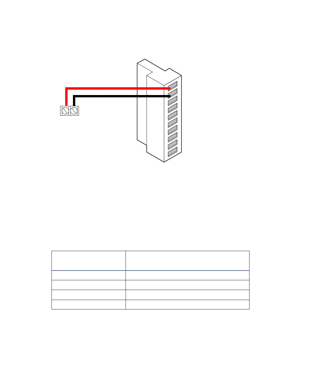
Connecting a chart recorder
Recorder signal
The A and B terminals on the detector’s rear panel provide 1-V analog output
signals that you can send to a chart recorder. To send a 1-V signal from the
detector to a chart recorder, use the cable in the startup kit to make the
connections in the following table and figure.
Tip: To minimize the chance of creating a ground loop that can adversely
affect measurement, connect the shield of the cable to the chassis ground at
one end only.
Detector inputs and chart recorder terminals
Chart recorder
terminals
2475 detector (B inputs and outputs)
+ Pin 1 Detector Out 1 + (1 V)
– Pin 2 Detector Out 1 – (1 V)
+ Pin 4 Detector Out 2 + (1 V)
– Pin 5 Detector Out 2 – (GND)
+
2475 detector
B (inputs and outputs)
1
2
3
4
5
6
7
8
9
10
+
−
+
−
+
−
+
−
Detector out 1
Detector out 1
Ground
Detector out 2
Detector out 2
Switch 1
Switch 1
Ground
Switch 2
Switch 2
746 data module
terminals
Red
Black