Connecting other devices 2-27
Connecting a 746 data module
You can connect a Waters 746 data module to the detector using the analog
output connector on the detector’s rear panel. The analog connector provides
1 V output, which is scaled to the EUFS sensitivity setting and the voltage
offset setting.
Tip: To prevent oversaturation of the signal from the detector to the data
module, do not exceed the input voltage rating of the data module.
To send the analog output signal from the detector to the data module, use the
cable provided in the detector’s startup kit to make the connections shown in
the following table and figure.
Tip: To minimize the chance of creating a ground loop that can adversely
affect measurement, connect the shield of the cable to the chassis ground at
one end only.
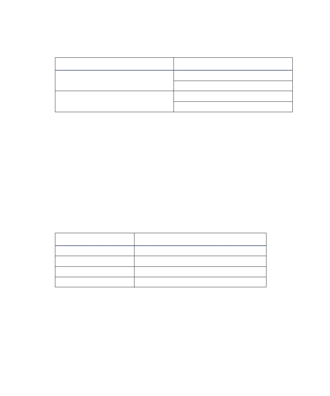
Detector connections to the Bus SAT/IN module
Bus SAT/IN connector 2475 detector (B outputs)
Channel 1 or 2 Pin 1 Detector Out 1 + (white)
Pin 2 Detector Out 1 – (black)
Channel 1 or 2 Pin 4 Detector Out 2 + (white)
Pin 5 Detector Out 2 – (black)
Detector inputs and 746 terminals
746 terminals 2475 detector (B inputs and outputs)
+ Pin 1 Detector Out 1 + (red)
– Pin 2 Detector Out 1 – (black)
+ Pin 4 Detector Out 2 + (red)
– Pin 5 Detector Out 2 – (black)