8-44 Phaser 6130 Color Laser Printer Service Manual
Service Parts Disassembly
Frame
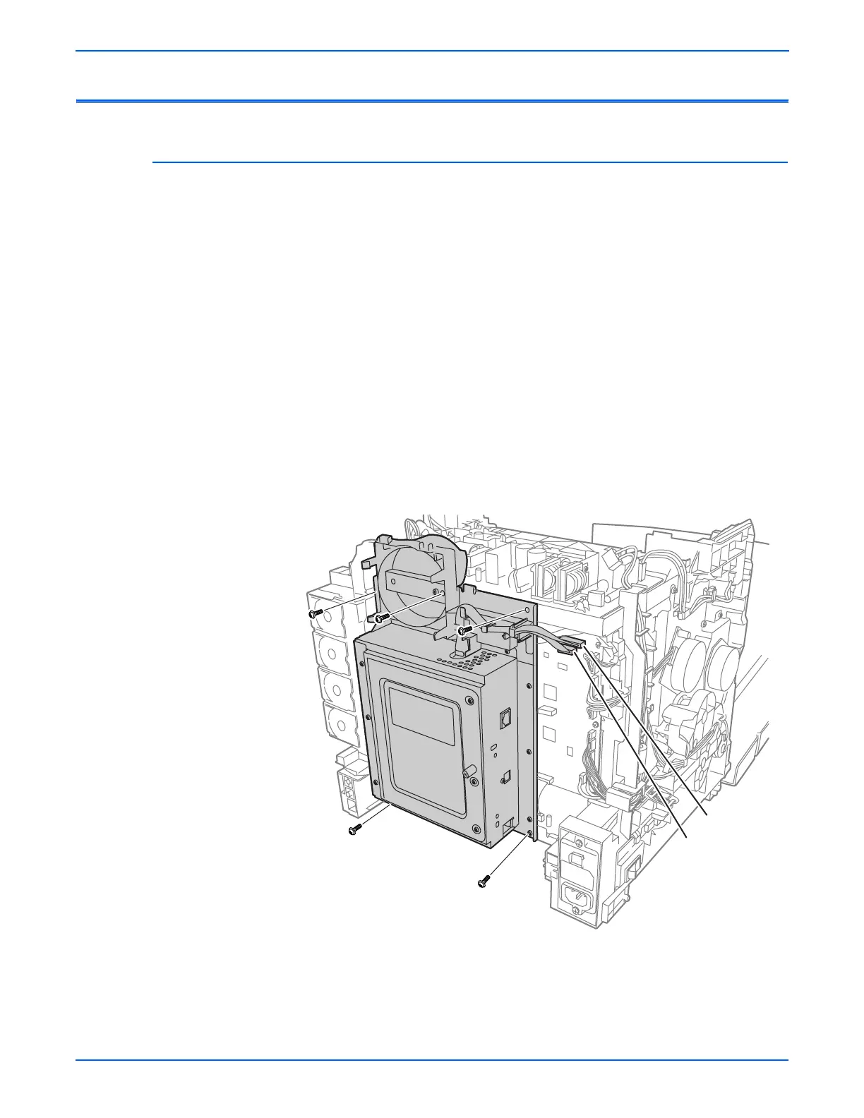
I/P Board Cage
This procedure removes the entire I/P board enclosure including the Fan
Duct. Although it is not associated with any one part, it is a necessary
prerequisite for other procedures.
1. Remove the Fan (page 8-56).
2. Remove the two screws with circles scribed around them at the bottom of
the Image Processor Frame.
3. Unplug the cables at P10 and P11 on the MCU board.
4. Disconnect P40 from the LVPS and release the harness from restraints.
5. Remove the three circled screws at the top of the Image Processor
Frame. (one screw is behind the Fan).
o
e
Loosening or removing the screw that holds the Fan Duct to the IP Board
Frame can ease the IP Board Frame removal. Do not remove the Fan
Duct.
6. Swing the assembly out from the bottom and lift up enough to free the
hook at the top.
P/J10
P/J11
s6130-141