8-26 Phaser 6130 Color Laser Printer Service Manual
Service Parts Disassembly
Left Harness Assembly
PL 3.1.18
o
e
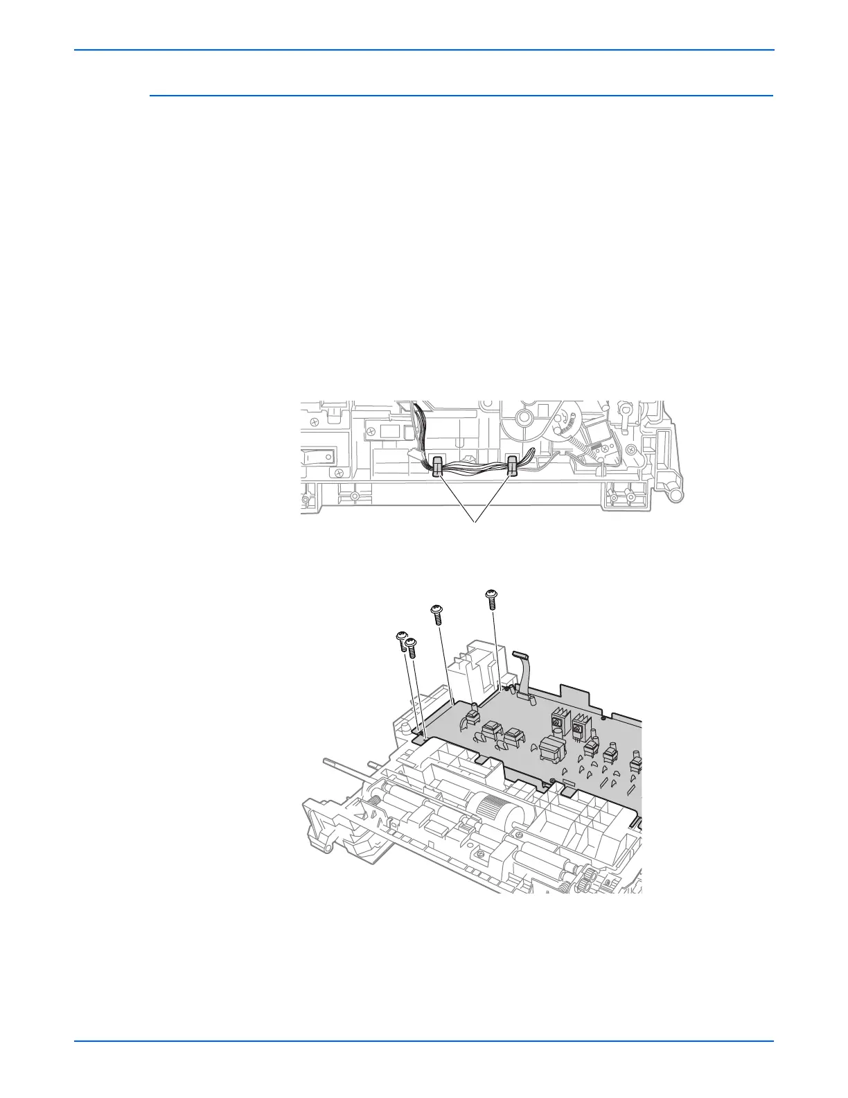
Pay close attention to the routing of the wires as they are removed from
the Feeder.
1. Remove the Manual Feed No Paper Sensor (page 8-28).
2. Remove the Drive Clutch Kit (page 8-21).
3. Remove the Feed Solenoid (page 8-24).
4. Separate the Upper and Lower Assemblies (page 8-47).
5. Release the Left Harness Assembly wires from the AC Harness Guide.
6. Remove the E-ring that retains the Feed Shaft assembly (PL3.2.2) in the
bearing on the Left Feeder Chassis.
7. Release the Left Harness Assembly from the hooks in the Left Feeder
Chassis.
8. Remove the four screws (silver, tap, 8mm) that secure the HVPS Frame to
the Left Feeder Chassis.
9. Remove the three screws (silver, tap, 8mm) that attach the Left Feeder
Chassis to the Regi Feeder Chute.
10. Separate the Left Feeder Chassis from the Regi Feeder Chute; pull the
Left Harness Assembly through the square hole in the Left Feeder
Chassis.
Hooks
s6130-221
s6130-224