Do you have a question about the Xerox PHASER 6130 and is the answer not in the manual?
Defines terms like Note, Caution, Warning used for information and safety.
Defines terms like Caution and Danger related to hazards.
Details voltage requirements and proper grounding for safe operation.
Explains when and how to safely disconnect the printer's power cord.
Lists techniques to reduce component damage caused by static electricity.
Provides essential safety advice for qualified service personnel.
Emphasizes reading and obeying all posted warning labels on the printer.
Stresses ensuring covers and interlock switches function correctly.
Explains the Class 1 laser classification and safety during servicing.
Provides a general overview of the Phaser 6130 Color Laser Printer's design and features.
Lists resources for updates, service bulletins, and technical support contacts.
Details the available features and configurations for the Phaser 6130 printer.
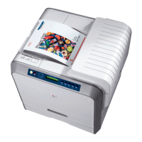
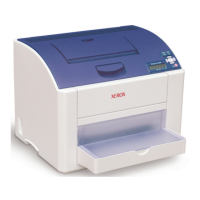
Identifies and illustrates the external parts of the printer.
Lists and describes available printer options such as memory and network cards.
Lists printer parts with limited life that require periodic replacement.
Describes the printer's consumables, primarily toner cartridges.
Provides detailed functional and performance specifications for the printer.
Details the printer's memory capacity and supported RAM types.
Lists electrical specifications including voltage, current capacity, and power consumption.
Provides print speed specifications based on resolution and paper type.
Specifies operating conditions for temperature, humidity, and altitude.
Describes the different operating modes of the printer: Running, Ready, and Power Saver.
Defines and lists FPOT specifications for color and mono printing.
Provides specifications for print area, skew, parallelism, linearity, magnification, and registration.
Lists printer dimensions and minimum clearance requirements for installation.
Details requirements for printer mounting surface flatness and tilt.
Lists supported paper sizes, types, weights, and envelopes.
Describes controller functions related to job management and print volume.
Explains RAM Disk functions and requirements for features like Collation and Secure Print.
Describes the function for writing PCL6 forms downloaded into RAM Disk.
Explains how PCL6 fonts can be downloaded into RAM Disk.
Describes the print counters for tracking color, mono, and total pages printed.
Explains how to position and print the User Name on the page.
Describes the mode where the printer stops accepting print requests when toner life ends.
Explains how CentreWare Internet Services and PrintingScout display toner remaining.
Describes the printer's maintenance functions, including firmware updates.
Explains the available diagnostic functions: Auto and Manual Diagnostics.
Describes printing information pages like Demo Page and Configuration Page.
Provides an overview of the Phaser 6130's full-color laser design and CMYK process.
Details the seven steps involved in the printer's electrophotographic print process.
Illustrates the paper path route through the printer from input to output.
Identifies and illustrates the components along the paper path.
Classifies major printer components by category for understanding their functions.
Describes the printer's operational modes: Ready, Printing, Sleep, and Deep Sleep.
Explains printer control functions like paper size detection and light quantity control.
Illustrates the power transmission paths for the Main Drive and Sub-Drive assemblies.
Explains how error messages and codes guide the troubleshooting process.
Provides steps to access and print the printer's error history report.
Describes the contents of the Error History Report for jam and system fail errors.
Outlines a service checklist for diagnosing and resolving printer problems.
Lists common abbreviations used in error messages for display space limitations.
Provides a summary table of errors, codes, messages, and page references for procedures.
Details troubleshooting procedures for flash memory errors on the Image Processor Board.
Troubleshooting steps when the printer memory is full and cannot continue printing.
Troubleshooting steps for errors related to Printer Command Language (PCL).
Troubleshooting steps for errors occurring on the Image Processor Board.
Troubleshooting steps for PAGEC time errors related to the Image Processor Board.
Troubleshooting steps for detected DIMM slot RAM errors.
Troubleshooting for errors related to toner cartridge detection, type, and level.
Troubleshooting procedures for various paper jam locations within the printer.
Troubleshooting steps for errors related to the Multi-Protocol Network Card.
Troubleshooting for CTD Sensor errors and Transfer Unit life status.
Troubleshooting for errors related to Imaging Unit installation and CRUM.
Troubleshooting steps for Front Cover and Side Door open errors.
Troubleshooting steps for MCU firmware and NVRAM errors.
Troubleshooting steps for errors detected in the Laser Unit.
Troubleshooting steps for MCU communication errors.
Troubleshooting for invalid job, download mode, K mode solenoid, and environment sensor errors.
Covers system startup, POST, service diagnostics, and troubleshooting non-error related issues.
Describes the typical printer startup sequence and its stages.
Lists and describes the diagnostic tests performed during the printer's power-on self-test.
Explains how to access and use the printer's built-in diagnostics.
Illustrates the navigation structure of the Service Mode menus.
Identifies and illustrates key mechanical components and sensors within the printer.
Lists diagnostic tests and their descriptions, including error codes and relevant tests.
Provides troubleshooting steps for control panel issues like 'Ready' state failures or blank displays.
Describes how to perform an engine test print to isolate hardware problems.
Guides for troubleshooting inoperable printers, including power-up sequence and warming-up issues.
Describes troubleshooting steps for AC power supply issues.
Details troubleshooting for LVPS overcurrent, overvoltage protection, and general LVPS issues.
Troubleshooting steps for the +24 VDC Interlock Switch.
Troubleshooting steps for identifying sources of abnormal noise and electrical issues.
Troubleshooting steps for common issues related to Windows OS and applications.
Procedures to eliminate cabling, communication, and connection problems for Mac OS.
Provides quick install steps and resources for connecting printers to UNIX/Linux systems.
Discusses print-quality defects attributed to components, consumables, media, and environment.
Lists common print-quality problems and the specific printer assemblies they are associated with.
Provides a checklist of printer conditions to examine before troubleshooting print quality.
Provides information on analyzing various test prints to determine output quality.
Details specifications for environmental conditions, paper quality, and printer settings.
Lists print-quality defects, their definitions, and corresponding procedure page numbers.
Covers procedures for adjusting printer settings like color registration.
Describes processes for initializing the print meter and NVRAM settings.
Explains how to read, write, and adjust printer parameter values.
Outlines procedures for checking, servicing, or repairing the printer for optimal operation.
Lists essential tools for performing service maintenance procedures.
Outlines general cleaning steps for printer maintenance.
Details routine maintenance procedures covering cleaning, inspection, and diagnostics.
Explains how to find removal procedures for field-replaceable parts and their organization.
Identifies the front, rear, left, and right sides of the printer for procedural clarity.
Lists essential steps and cautions before starting any removal or replacement procedure.
Explains notations used in disassembly procedures and illustrations.
Lists common screw types used in printer assembly with dimensional specifications.
Lists key maintenance items and consumables for the printer.
Provides instructions for removing the Imaging Unit, with cautions about light exposure.
Describes the removal of the Fuser, including warnings about heat and end-of-life procedures.
Provides instructions for removing the toner cartridges.
Details removal procedures for various printer covers, including Toner Access Door.
Describes the removal of the Rear Tray Cover.
Describes the removal of the Cassette Stopper.
Provides instructions for removing the Control Panel.
Describes the removal of the Top Cover, including cautions and reassembly notes.
Provides instructions for removing the Output Tray Extension.
Describes the removal of the Right Side Cover.
Describes the removal of the Left Side Cover.
Describes the removal of the Rear Cover.
Provides instructions for removing the Front Cover.
Details removal procedures for paper feeder components, starting with the Drive Clutch Kit.
Provides instructions for removing the Feed Drive Assembly.
Details the removal of the Left Harness Assembly, paying attention to wire routing.
Describes the removal of the Manual Feed No Paper Sensor, with cautions for the Transfer Belt.
Provides instructions for removing the Feed Roller, with notes on orientation.
Details removal procedures for xerographic components, starting with the Laser Unit.
Provides instructions for removing the Dispenser Assembly.
Details the removal of the Erase LED Assembly.
Describes the removal of the Right Imaging Unit Restraint Block.
Describes the removal of the Left Imaging Unit Restraint Block.
Provides instructions for removing the Toner Cartridge Holder.
Describes the removal of the Transfer Unit, with cautions for belt surface and harness connections.
Provides instructions for removing the HVPS Board.
Details the removal of the I/P Board Cage, including fan duct and associated screws.
Describes the removal of the Transfer Unit pivot shafts, with notes on handling gears.
Describes separating printer assemblies as a prerequisite for other part removals.
Details removal procedures for drive system components, starting with the Main Drive Assembly.
Provides instructions for removing the Sub-Drive.
Details removal procedures for electrical components like harness assemblies.
Explains the format and location of the printer's serial number for part ordering.
Explains how to use the parts list, including ID numbers, descriptions, and abbreviations.
Lists and illustrates part numbers for the printer's covers.
Lists and illustrates parts related to the Paper Tray assembly.
Lists and illustrates parts for the Paper Feeder assembly.
Lists and illustrates additional parts for the Paper Feeder assembly.
Lists and illustrates parts related to the Xerographics assembly.
Lists and illustrates parts for the Dispenser assembly.
Lists and illustrates parts for the Transfer Unit and Fuser.
Lists and illustrates parts related to the printer's drive system.
Lists and illustrates electrical components of the printer.
Lists and illustrates additional electrical components of the printer.
Lists and illustrates the printer's various wiring harnesses.
Lists part numbers for Xerox supplies, maintenance items, options, and kits.
Lists contents and part numbers for hardware and packaging service kits.
Explains how to interpret plug/jack designators and their purpose in troubleshooting.
Lists P/J connector designators for the print engine, their map locations, and remarks.
Provides visual maps indicating the location of key connections within the printer.
Lists additional P/J connector designators, their map coordinates, and remarks.
Lists further P/J connector designators, their map coordinates, and remarks.
Shows wiring diagrams for feeder, manual feed, registration, drive, developer, and toner harnesses.
Shows wiring diagrams for the Laser Unit, including RE and Video harnesses.
Shows wiring diagrams for MCU, Imaging Unit, Humidity Sensor, LVPS, Left Side Harness, and Transfer Assembly.
Shows the wiring diagram for the High Voltage Power Supply connections.
Shows wiring diagrams for MCU connections to toner motors and CRUM harnesses.
Shows wiring diagrams for Fuser connections to MCU, LVPS, and related components.
Shows wiring diagrams for IP Board, MCU Board, Control Panel, and LVPS connections.
Explains symbols used in wiring diagrams, including plugs, jacks, jumpers, and parts.
Illustrates the navigation structure of the printer's control panel menus.
Provides instructions for updating the printer's firmware via USB.
Lists common acronyms and abbreviations used in the manual with their descriptions.
| Color | Yes |
|---|---|
| Print technology | Laser |
| Maximum resolution | 2400 x 600 DPI |
| Warm-up time (from sleep mode) | 25 s |
| Time to first page (black, normal) | 14 s |
| Time to first page (color, normal) | 17 s |
| Print speed (black, normal quality, A4/US Letter) | 16 ppm |
| Print speed (color, normal quality, A4/US Letter) | 12 ppm |
| Maximum internal memory | 1152 MB |
| Sound power level (standby) | 25.7 dB |
| Sound pressure level (printing) | 51.6 dB |
| Total input capacity | 250 sheets |
| Total output capacity | 150 sheets |
| Maximum input capacity | 251 sheets |
| Media weight (tray 1) | 64 - 220 gsm |
| Multi-Purpose Tray media weight | 64 - 164 g/m² |
| Functions | |
| I/O ports | 10/100BaseTX Ethernet, USB 2.0 |
| Device manager | Auto IP, BOOTP/RARP, DHCP, PrintingScout Alert Notification, SNMP v.2, Xerox CentreWare Internet Services Embedded Web Server, Email alerts |
| Package length | 558.79 mm |
| Depth (imperial) | 17.5 \ |
| Width (imperial) | 15.75 \ |
| Height (imperial) | 15.3 \ |
| Security features | Secure Print |
| Power requirements | 220–240 VAC, 50/60 Hz |
| Networking features | 10/100 Base-TX Ethernet |
| Color space standard | ICM, ICC, PANTONE Color Approved |
| Enhanced scan resolution | 600 x 600 DPI |
| Storage temperature (T-T) | 32 - 95 °F |
| Power consumption (active) | 280 W |
| Compatible operating systems | Windows 2000/2003 Server/XP/XP Home Edition (SP1 +)/ Vista, Mac OSX 10.2 +, Linux: SUSE 9.2 +/Turbo Linux 10/ Red Hat ES3 +/Fedora Core/Yellow Dog 3.X |
| Acoustic power emissions (standby) | 43 dB |
| Non-operating relative humidity (non-condensing) | 15 - 85 % |
| Acoustic power emissions (active, print, copy or scan) | 64.6 dB |
| PCL fonts | 81 |
| Printer fonts | PCL, PostScript |
| Country of origin | China |
| Maximum duty cycle | 40000 pages per month |
| Recommended duty cycle | 3000 pages per month |
| Number of PostScript fonts | 136 |
| Sustainability certificates | ENERGY STAR |
| Power consumption (standby) | 50 W |
| Power consumption (PowerSave) | 5 W |
| Operating temperature (T-T) | 5 - 32 °C |
| Operating relative humidity (H-H) | 15 - 80 % |
| Certification | FCC 15 B, UL 60950-1/CSA 60950-1-03, CE Mark 73/23/EEC, 89/336, EEC, Section 508 ADA |
| Package width | 533.39 mm |
| Package height | 507.99 mm |
| Package weight | 22226.4 g |
| Depth | 445 mm |
|---|---|
| Width | 400 mm |
| Height | 389 mm |
| Dimensions (WxDxH) | 400 x 394 x 389 mm |


