Phaser 6130 Color Laser Printer Service Manual 8-61
Service Parts Disassembly
5. Remove the screw (silver, 4mm) that attaches the USB connector on the
Image Processor Board to the I/O Plate.
6. Remove the two screws (silver, 6mm) that attach the Image Processor
Board to the I/O Plate and separate the two pieces.
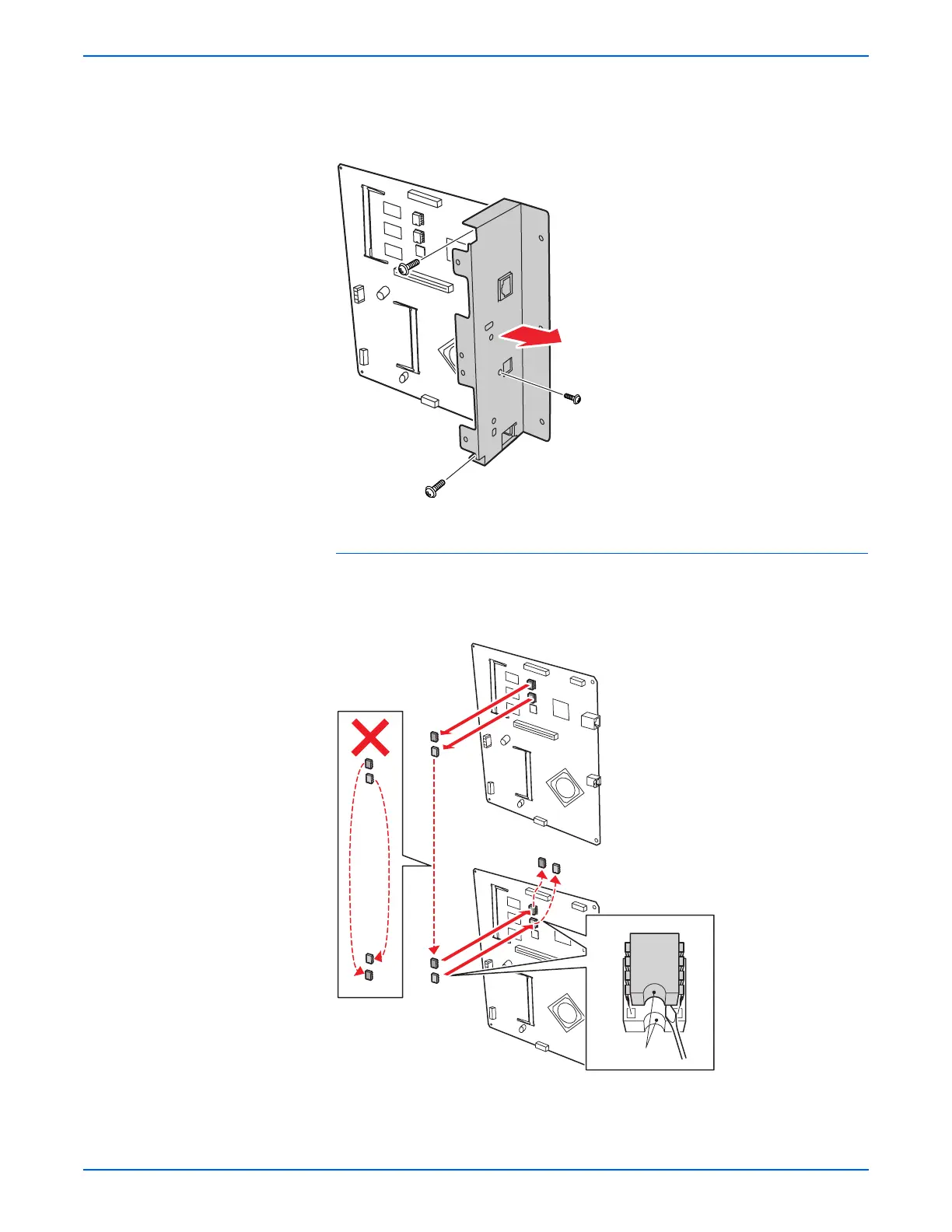
Reassembly Note
When installing a new I/P Board, be sure to move the NVRAM chips from the
old I/P Board to the new I/P Board. Carefully check the correct location and
orientation of each NVRAM chip when installing.
s6130-162
Old Image Processor Board
New Image Processor Board
Notch
s6130-169