08/2012
6-96
WorkCentre 5021/5019
6.4.2.5, 6.4.2.6
Initial Issue
General Procedures
Figure 2 j0lj64004
5. When the initialization has completed successfully, [End] will flash twice -> remain ON to
indicate the completion of the [NVM] initialization.
6. Pressing the [Clear All] button returns you to the [Chain-Link Number Entry] screen.
6.4.2.6 Component Check (IOT/IIT/DADF)
Purpose
Displays the logic state of Input Component input signals and operates the Output Compo-
nents.
NOTE: For more details on the Component Check Code, refer to 6.3.1 and 6.3.2 in Chapter 6.
Procedure
<Input Component Check>
1. Enter the CE Diag Mode.
2. Input the Chain-Link No. and press the [Start] button.
• The value is refreshed in 1/3 second.
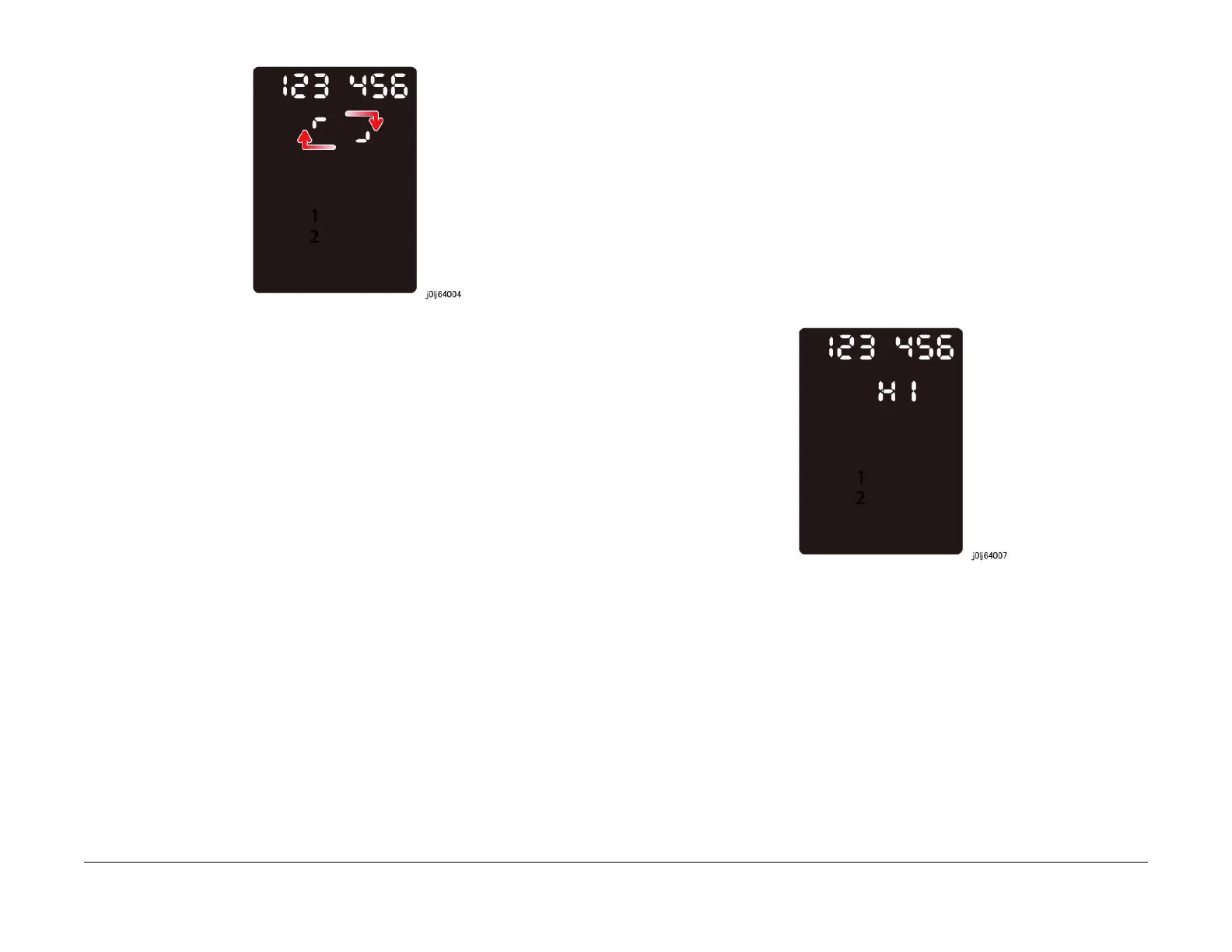
3. The result of Input Check is displayed as 'HI' for High Level and 'LO' for Low Level.
• Example of High Level
Figure 1 j0lj64007
4. Pressing the [Stop] button causes the [End] to flash twice -> remain ON to indicate that
the Input Check has completed.
5. Pressing the [Clear All] button returns you to the [Chain-Link Number Entry] screen.
<Output Component Check>
1. Enter the CE Diag Mode.
2. Input the Chain-Link No. and press the [Start] button.
• When an Output Component is in operation, an animation will be displayed to indi-
cate that it is in progress.

 Loading...