204 www.xilinx.com Virtex-5 RocketIO GTP Transceiver User Guide
UG196 (v1.3) May 25, 2007
Chapter 10: GTP-to-Board Interface
R
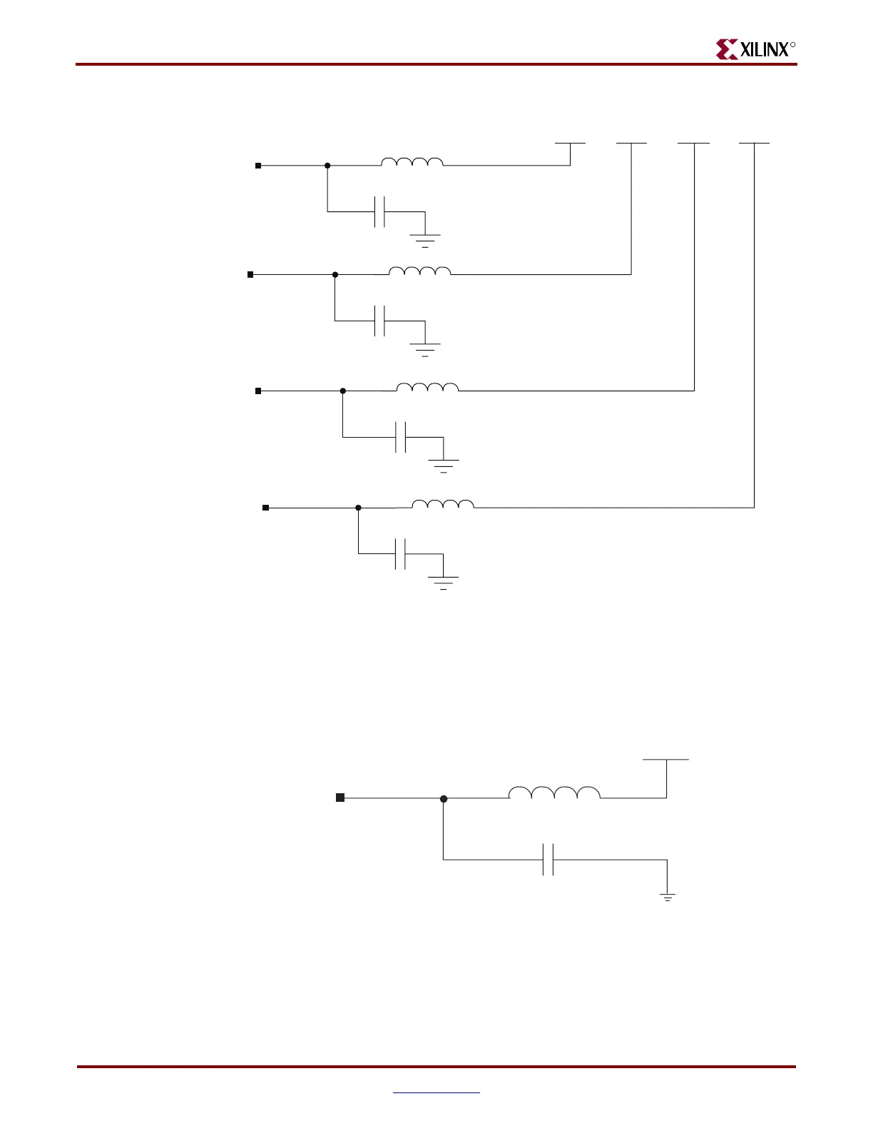
Figure 10-4 illustrates the power filter network for the MGTAVTTRXC pin.
Figure 10-3: Power Filtering Schematic
Figure 10-4: Power Filter Network for MGTAVTTRXC
114_MGTVTTRX
114_MGTVTTTX
114_MGTAVCC
114_MGTAVCC_PLL
FERRITE-220 (220Ω @ 100 MHz)
1.2V
AVTTRX
(1)
1.2V
AVTTTX
(1)
1.0V
AVCC
(1)
1.2V
AVCC_PLL
(1)
0.22 μF
10VX7R
FERRITE-220 (220Ω @ 100 MHz)
0.22 μF
10VX7R
FERRITE-220 (220Ω @ 100 MHz)
0.22 μF
10VX7R
FERRITE-220 (220Ω @ 100 MHz)
0.22 μF
10VX7R
UG196_c10_03_041907
Notes:
1. These analog supplies MUST be sourced directly from a dedicated regulator. Derived voltages from
other supplies or resistor voltage dividers are NOT permitted.
MGTAVTTRXC
1.2V
AVTTRX
(1)
L33
UG196_c10_04_041907
1
1
2
2
FERRITE-220
(220Ω @ 100 MHz)
X7R 10V
0.22 μF
C62
Notes:
1. This analog supply MUST be sourced directly from a dedicated regulator. Derived voltages from other
supplies or resistor voltage dividers are NOT permitted.
 Loading...

