240 www.xilinx.com Virtex-5 RocketIO GTP Transceiver User Guide
UG196 (v1.3) May 25, 2007
Chapter 13: Design of Transitions
R
3D field solver analysis or measurement along with several board iterations to get the
desired performance.
The 2D field solver example shows that close to 50Ω can be achieved if the ground plane
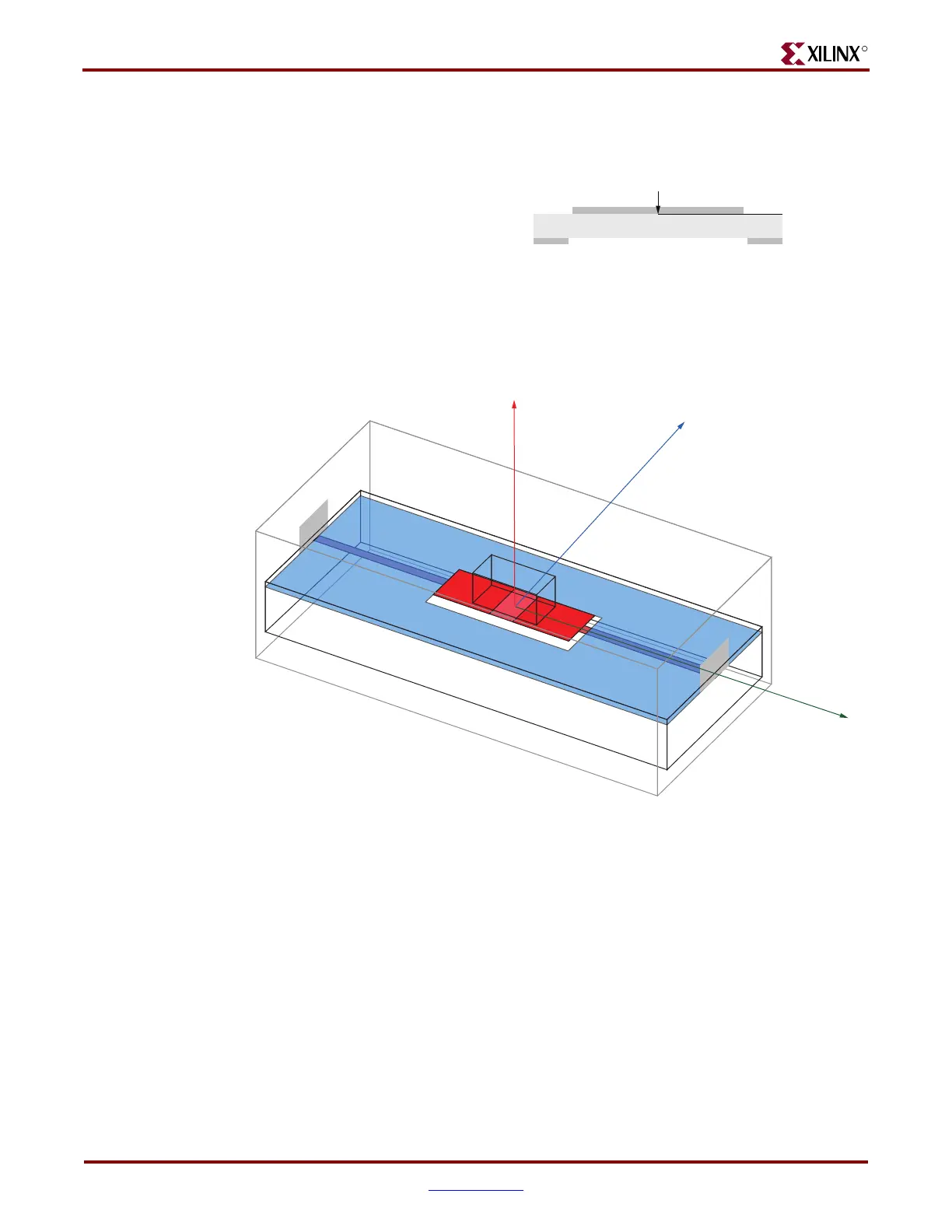
under the pad footprint is cleared out. A 3D field solver is then used to verify this result to
a greater degree of accuracy.
Figure 13-6 shows the ground plane cleared away exactly as it was for the 2D simulation.
Using frequency domain analysis within HFSS, there is a 20 dB (10x) improvement in
return loss using this technique. The approximately -40 dB/decade slope in Figure 13-8
shows good fit to the frequency response of a lumped capacitor.
Figure 13-5: Transition Optimization
Figure 13-6: Ansoft HFSS Model of Pad Clear-Out
- L = 241 nH/m
- C = 89 pF/m
- Zo = 52Ω
28 Mil Pad
UG196_c13_05_051406
UG196_c13_06_051406
Z
Y
X
 Loading...

