28 www.xilinx.com Virtex-5 RocketIO GTP Transceiver User Guide
UG196 (v1.3) May 25, 2007
Chapter 1: Introduction to the RocketIO GTP Transceiver
R
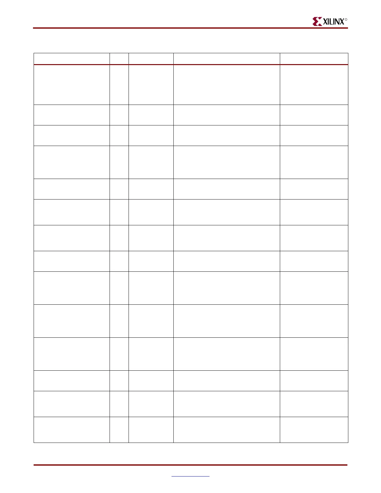
RXENSAMPLEALIGN0
RXENSAMPLEALIGN1
In RXUSRCLK2
When High, the 5X oversampler in the
PCS continually adjusts its sample
point. When Low, it samples only at the
point that was active before the port
went Low.
Oversampling
(page 143)
RXEQMIX0[1:0]
RXEQMIX1[1:0]
In Async
Sets the wideband/high-pass mix ratio
for the RX equalizer.
RX Termination and
Equalization (page 125)
RXEQPOLE0[3:0]
RXEQPOLE1[3:0]
In Async
Sets high-pass filter pole location for
the RX equalizer.
RX Termination and
Equalization (page 125)
RXLOSSOFSYNC0[1:0]
RXLOSSOFSYNC1[1:0]
Out RXUSRCLK2
FPGA status related to byte stream
synchronization, depending on the
state of the RX_LOSS_OF_SYNC_FSM
attribute.
Configurable Loss-of-
Sync State Machine
(page 155)
RXNOTINTABLE0[1:0]
RXNOTINTABLE1[1:0]
Out RXUSRCLK2
Indicates if RXDATA is the result of an
illegal 8B/10B code and is in error.
Configurable 8B/10B
Decoder (page 157)
RXOVERSAMPLEERR0
RXOVERSAMPLEERR1
Out RXUSRCLK2
Indicates the FIFO in oversampling
circuit has either overflowed or
underflowed.
Oversampling
(page 143)
RXPMASETPHASE0
RXPMASETPHASE1
In RXUSRCLK2
Aligns the PMA receiver recovered
clock with the PCS user clocks,
allowing the RX FIFO to be bypassed.
Configurable RX Elastic
Buffer and Phase
Alignment (page 162)
RXPOLARITY0
RXPOLARITY1
In RXUSRCLK2 Inverts the polarity of incoming data.
RX Polarity Control
(page 146)
RXPOWERDOWN0[1:0]
RXPOWERDOWN1[1:0]
In Async Powers down RX lanes.
Power Control
(page 81), PCI Express
Receive Detect Support
(page 117)
RXPRBSERR0
RXPRBSERR1
Out RXUSRCLK2
Indicates if the number of errors in
PRBS testing exceeds the value set by
the PRBS_ERR_THRESHOLD
attribute.
PRBS Detection
(page 147)
RXRECCLK0
RXRECCLK1
Out N/A
Recovered clocks derived from the RX
Clock Data Recovery circuit. Clocks the
RX logic between the PMA and the RX
elastic buffer.
FPGA RX Interface
(page 182)
RXRESET0
RXRESET1
In Async Active-High reset for the RX PCS logic.
Reset (page 73), FPGA
RX Interface (page 182)
RXRUNDISP0[1:0]
RXRUNDISP1[1:0]
Out RXUSRCLK2
Shows the running disparity of the
8B/10B encoder when RXDATA is
received.
Configurable 8B/10B
Decoder (page 157)
RXSLIDE0
RXSLIDE1
In RXUSRCLK2
Implements a comma alignment bump
control, allowing manual comma
alignment.
Configurable Comma
Alignment and
Detection (page 150)
Table 1-3: GTP_DUAL Port Summary (Continued)
Port Dir Domain Description Section (Page)
 Loading...

