78 www.xilinx.com Virtex-5 RocketIO GTP Transceiver User Guide
UG196 (v1.3) May 25, 2007
Chapter 5: Tile Features
R
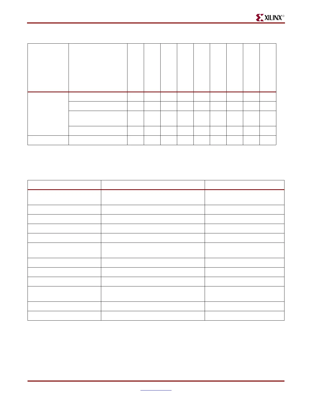
The reset that occurs after configuration and the GTPRESET port are the most common
ways to prepare GTP_DUAL(s) for operation, but certain situations can require the use of
other reset ports. Table 5-8 outlines some of these situations, and the recommended resets.
RX PMA SIPO ✓✓✓ ✓ ✓
RX CDR ✓✓✓ ✓ ✓
RX Termination and
Equalization
✓✓✓
RX OOB ✓✓✓ ✓
Loopback Loopback paths ✓✓✓
Table 5-7: Available Resets Pins and the Components Reset by These Reset Pins (Continued)
Component
Configuration
GTPRESET
PLLPOWERDOWN
(Falling Edge)
TXRESET
RXCDRRESET
RXRESET
RXBUFRESET
RXELECIDLERESET
PRBSCNTRESET
Table 5-8: Recommended Resets for Common Situations
Situation Components to be Reset Recommended Reset
(1)
Power Up and Configuration Entire GTP_DUAL tile Reset after configuration is
automatic.
Turning on a reference clock Shared PLL GTPRESET
Changing a reference clock Shared PLL GTPRESET
Parallel clock source reset TX PCS, RX PCS, Phase Alignment TXRESET, RXRESET
Remote Power Up RX CDR RXELECIDLERESET
SATA OOB / PCI Express
Electrical Idle
RX CDR RXELECIDLERESET
Connecting RXN/RXP RX CDR RXELECIDLERESET
After a TX buffer error TX Buffer TXRESET
After an RX buffer error RX Buffer RXBUFRESET
Before channel bonding RX CDR, then RXBUFFER after CDR is locked RXELECIDLERESET,
RXBUFRESET
PRBS error PRBS Error counter PRBSCNTRESET
Over-sampler error Over-sampler RXRESET
Notes:
1. The recommended reset has the smallest impact on the other compents of the GTP_DUAL tile.
 Loading...

