FEATURES
EA$20170
FEATURES
EA$1AC1101
OUTLINE
OF
THE Fl SYSTEM
The
ma
in funct
ion
of
a fuel
supp
ly system is to provide fuel to
the
comb
ust
ion
chamber
at
the
opt
i
mum
air-fuel ratio in accordance with the engine operat
ing
co
nd
i
ti
ons
and
the
atmosp
he
ric temperature. In
the conventional carburetor system, t
he
air-fuel ratio
of
the
mix
ture
tha
t is supplied to t
he
com
bustion
chamber
is
created
by
the vol
ume
of t
he
int
ake
air
and
t
he
fuel
tha
t is
me
t
ered
by
the
j
et
used in t
he
res
pec
tive carburetor.
Despite t
he
sam
e volume
of
intake air, t
he
fuel vol
ume
requirement
var
ies
by
t
he
engine operating con-
dit
i
ons
, such as acceleration,
dec
eleration,
or
ope
rating
under
a
he
avy load. Carburetors t
hat
meter t
he
fuel thro
ug
h the
use
of
je
ts have b
een
prov
ided with various auxili
ary
d
ev
ices, so that
an
optimum air-fu-
el ratio
can
be
ach
ieved to accommodate the constant
cha
nges in the
ope
rati
ng
conditions of
th
e en-
gine.
As the requirements f
or
the engine to
de
li
ver
more
performance
and
cle
aner
exhaust gases increase,
it b
eco
mes
ne
cessary to
con
trol t
he
air-fuel r
at
io in a
more
precise a
nd
finely tuned manner.
To
accom-
modate
this need, this model
has
a
do
pted an electronica
ll
y controlled fuel injection (Fl) system, in place
of
the conventional carburetor system.
Th
is system
can
achieve an
opt
imum air-fuel rat
io
requ
ir
ed by
the eng
ine
at all times by usi
ng
a microprocessor that regulates the fuel injection vol
um
e accordi
ng
to
the engine operating conditions
detec
ted by
va
ri
ous sensors.
The
adoption
of
t
he
Fl syst
em
has resulted in a highly precise fuel suppl
y,
improved engine response,
better f
uel
economy, and reduced exhaust
em
i
ss
ions.
1 2
3,4
,
5,6
7 8
9
17
15, 16 14 13 12
11
10
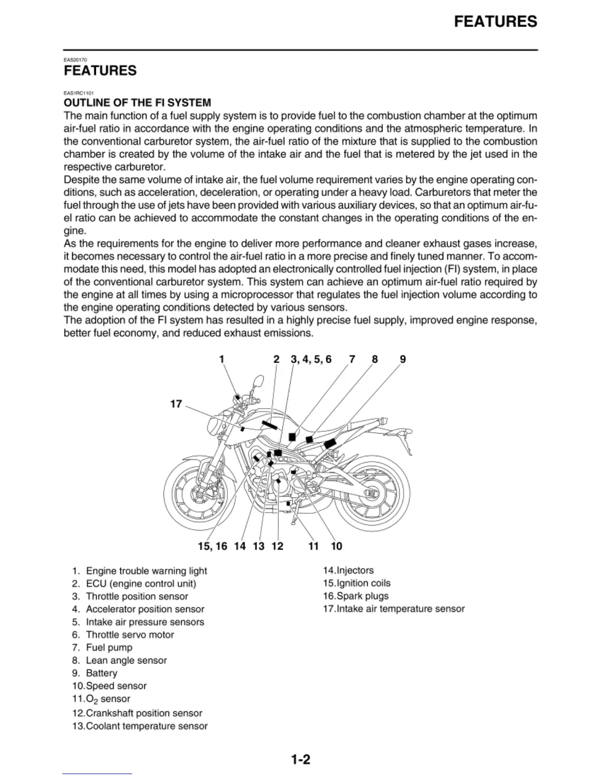
1. Engine
tr
ouble warning light
2.
ECU
(engine control
un
i
t)
3. T
hr
ottle
po
sition sensor
4. Accelerat
or
po
sition sensor
5.
In
ta
ke air pressure sensors
6.
T
hr
ottle ser
vo
mo
tor
7.
Fu
el pump
8.
Lean angle sensor
9.
Ba
tt
ery
10.
Sp
ee
d sensor
1
1.0
2
sen
so
r
12.
Crankshaft
po
siti
on
sensor
1
3.
Coolant temperature sensor
14.lnjectors
1
5.
Ignition coils
16. Spark plugs
17.lntake air temperature sensor
1-2