• Do
not
allow carbon
depos
its
or
other
for
-
eign materials
to
enter any
of
the
passages
in
each throttle
body
or
in
the
space
be-
tween
the
throttle valve s
haft
and the
throt
-
tle
body
.
f. Aft
er
removi
ng
the carbon deposits, clean the
inside of
th
e throttle bodi
es
with the recom-
mended cleani
ng
solvent, and then dry the
throttle bodi
es
using compressed air
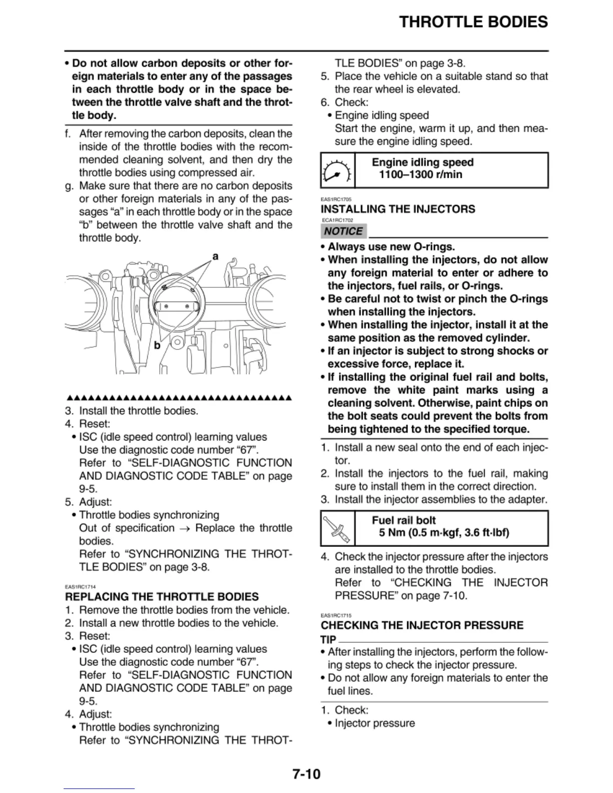
g. Make sure that there are
no
carbon deposits
or other foreign materials in any of the pas-
sages "a" in each throttle body or in the space
"b" between the throttle valve shaft and the
throttle body.
a
••••••••••••••••••••••••••••••••
3. Install the throttle bodies.
4. Reset:
• ISC (idle speed contro
l)
lea
rni
ng
va
lues
Use the diagnostic code number "67".
Refer to "SELF-DIAGNOSTIC
FU
NCTI
ON
AND
DI
AGNOSTIC CODE TABLE" on page
9-5.
5. Adjus
t:
• Throttle bodi
es
sy
nchroni
zi
ng
Out of spe
ci
fication -+
Re
pl
ace the
th
ro
ttle
bodies.
Refer to "SYNCHRONIZING THE THROT-
TLE BODIES" on page 3-
8.
EA$1AC171~
REPLACING THE THROTTLE BODIES
1. Remove the th
ro
ttle bodies from t
he
vehicle.
2. Install a new th
ro
ttle bodi
es
to the vehicl
e.
3. Reset:
• ISC (idle speed control) lea
rni
ng
va
lues
Use the diagnostic code number "67".
Refer to "SELF-DIAGNOSTIC FUNCTI
ON
AND
DI
AGNOSTIC CODE TABLE" on page
9-5.
4. Adjus
t:
• Throttle bodi
es
syn
ch
ronizing
Refer to "SYNCHRONIZING THE THROT-
THROTILE BODIES
TLE BODIES" on page 3-
8.
5. Place the ve
hi
cle on a s
ui
table stand so that
the rear wheel is elevat
ed.
6.
Check:
• En
gi
ne id
li
ng speed
Start the engine, warm it up, and then mea-
sure t
he
engine idling speed.
Engine idling speed
1100-1300
r/min
INSTALLING THE INJECTORS
ECAIRCl702
NOTICE
• Always use new
0-rings.
• When installing the injectors,
do
not
allow
any
foreign material
to
enter
or
adhere
to
the
in
ject
ors
, fuel rails,
or
0-r
i
ng
s.
• Be careful
not
to
twist
or
pinch
the
0-rings
when
installing
the
in
jectors.
• When installing
the
injector, install
it
at
the
same
posit
ion as
the
removed cyllnder.
• If an Injector
Is
subject
to
strong
s
hocks
or
exces
sive
force, replace It.
• If
installing
the original fuel rail and
bolts
,
remove the white paint
marks
using
a
cleaning solvent. Otherwise,
paint
chips
on
the
bolt
seats
could
prevent the
bolts
from
being tightened
to
the specified torque.
1. Insta
ll
a new seal onto the end of each injec-
tor.
2.
Insta
ll
the injectors to the fuel rail, making
sure to install them in the correct direction.
3. Insta
ll
the inject
or
assemb
li
es
to the adapt
er.
Fuel rail
bolt
5 Nm (0.5 m·kgf, 3.6 ft·lbf)
4. Check the injector pressu
re
after the injectors
ar
e installed to the throttle bodies.
Re
fer to "CHECKING THE
IN
JECTOR
PRESSURE" on page
7-
10
.
EA.SIFIC17l5
CHECKING THE INJECTOR PRESSURE
TIP
~~~~~~~~~~~~~~-
• After insta
ll
ing t
he
in
jectors, perform t
he
follow-
ing steps to check the injector pressure.
•
Do
not all
ow
any foreign materials to enter the
fuel lines.
1. Check:
•
In
jector pressure
7-10



 To Next Page