Headlight
relay
,........,....._,
,,.
3
Bri\V
2
1.
Pos
itive battery terminal
2. Negative battery terminal
3.
Pos
itive test
er
probe
4. Negative test
er
probe
Result
Continuity
(between "3"
and
"4")
Radiator
fan
motor
relay
-=-
2
1.
Positive batte
ry
terminal
2. Negative battery terminal
3.
Pos
itive test
er
probe
4. Negative test
er
probe
Result
Continuity
:>..
~
.
f
(between "3"
and
"4")
EAS
1
RCl80
1
4
1
, 3
4
1
CHECKING THE TURN SIGNAUHAZARD
RELAY
1. Ch
ec
k:
• Tum sign
aV
hazard
re
l
ay
input voltage
Out of specification
--t
The wiring ci
rc
ui
t from
the ma
in
switch to the
tu
rn
signaVhazard re-
l
ay
co
upler is faulty and must
be
repaired.
Turn
signaVhazard
relay
input
voltage
DC
12V
ELECTRICAL COMPONENTS
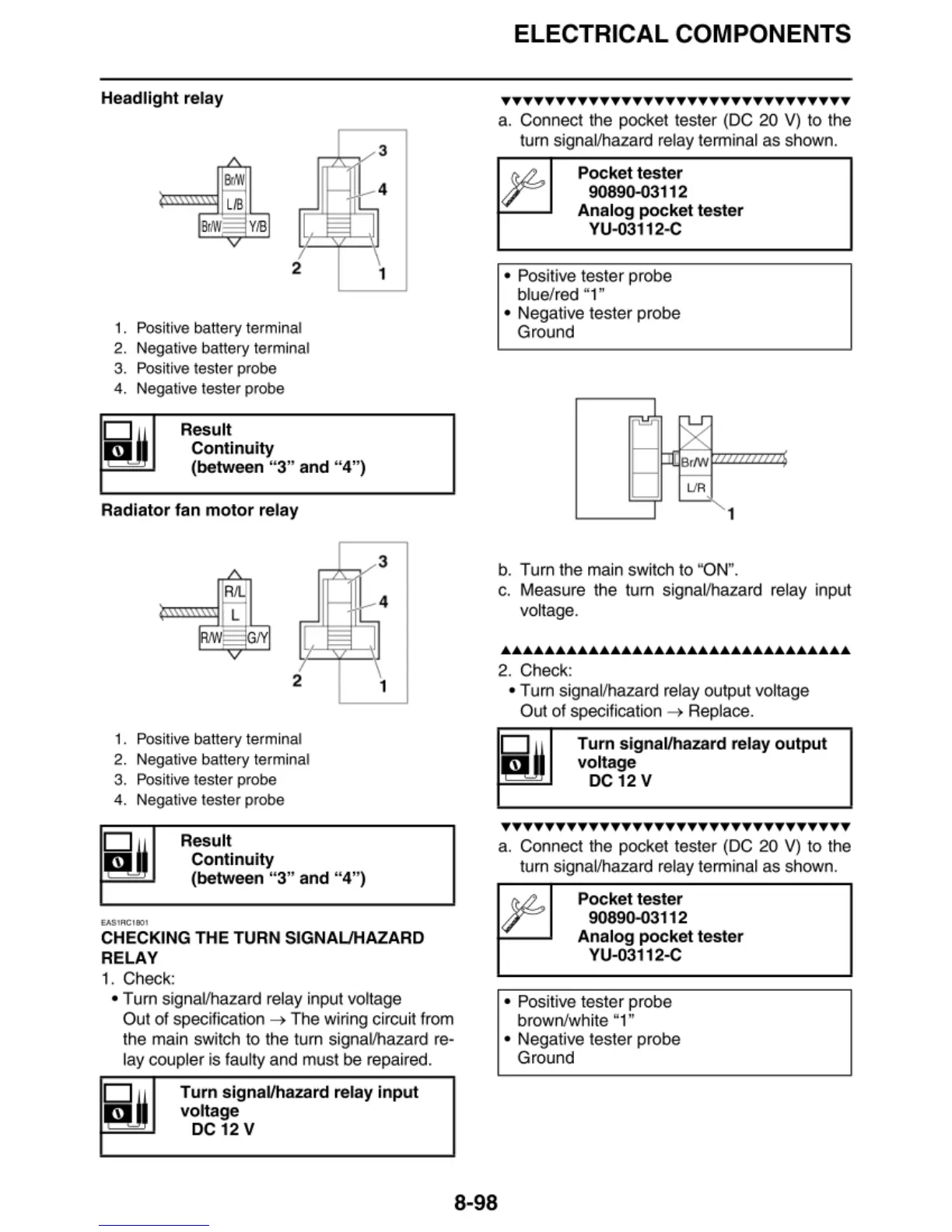
TTTTTTTTTTTTTTTTTTTTTTTTTTTTTTTT
a. Connect the pocket tester (DC 20 V) to the
tum signal/hazard relay terminal
as
shown.
Pocket
tester
90890-03112
Analog
pocket
tester
VU-03112-C
• Positive tester probe
blue/red "1"
• Negative tester probe
Ground
UR
1
b.
Tu
rn
the
ma
in
sw
itch to "ON".
c. Measure the tum signal/hazard
re
l
ay
input
voltage .
••••••••••••••••••••••••••••••••
2. Check:
• Tum signal/hazard relay output voltage
Out
of
specification
--t
Replace.
Turn
signal/hazard relay
output
voltage
DC
12V
TTYTTTYYTTTYTTTYYTTTYTTTYTTTYYTT
a. Connect
th
e pocket tester (DC 20
V)
to the
tu
rn
signal/hazard relay te
rm
inal
as
shown.
Pocket
tester
90890-03112
Analog
pocket
tester
VU-03112-C
• Positive tester pr
ob
e
brown
/w
hite "1"
8-98
• Negative tester probe
Ground