CRANKSHAFT AND BALANCER SHAFT
e. Install the balancer shaft journal lower
bear
-
ings
"1" into the lower crankcase and assem-
ble the crankcase halves.
TIP
---------------
• Align the projections "a" of the balancer shaft
journal lower bearings with the notches "b" in
the crankcase.
•
Do
not move the balancer shaft until the clear-
ance measurement has been completed.
f. Tighten the bolts to specification
in
the tight-
ening sequence cast on the crankcase. Refer
to "CRANKCASE" on page
5-56.
g. Remove the lower crankcase and the
ba
lanc-
er shaft journal lower bearings.
h. Measure t
he
compressed Plastigauge®
width "a" on each balancer shaft journal. If the
balancer shaft-
jo
urnal-to-balancer shaft-jour-
nal-bearing clearance is
ou
t
of
specification,
select replacement bala
ncer
shaft
jo
ur
na
l
bearings.
~
/,,
~
1v-....
a
~l
J
••••••••••••••••••••••••••••••••
4.
Select:
• Balancer shaft journal bearings
(J
1
-J
2
)
TIP
---------------
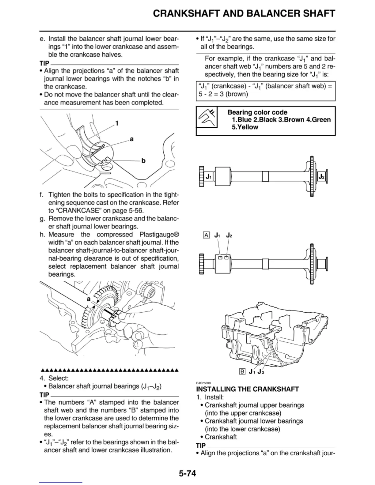
• The numbers "A" stamped into the balancer
shaft web and the numbers "B" stamped into
the lower crankcase are used to determine the
replacement balancer shaft journal bearing siz-
es.
• "J
1
"- "
J
2
" refer to the bearings shown in the bal-
ancer shaft and lower crankcase illus
tr
ation.
• If
"J(
-" J
2
" are the same, use the same size for
a
ll
of the bearings.
For exampl
e,
if the crankcase "J
,"
and bal-
ancer shaft
web
"J
( numbers are 5 and 2 re-
spectively, then the bearing size for
"J
( is:
"J
1
"
(crankcase) - "J
1
"
(balancer sha
ft
web)=
5 - 2 = 3 (brown)
"""""
Bearing color
code
1.Blue 2.Black 3.Brown 4.Green
5.Yellow
INSTALLING THE CRANKSHAFT
1.
Insta
ll
:
• Crankshaft journal upper bearings
(into the upper crankcase)
• Crankshaft journal lower bearings
(into the lower crankcase)
• Crankshaft
TIP
--------------~
• Align the projections "a" on the crankshaft jour-
5-74