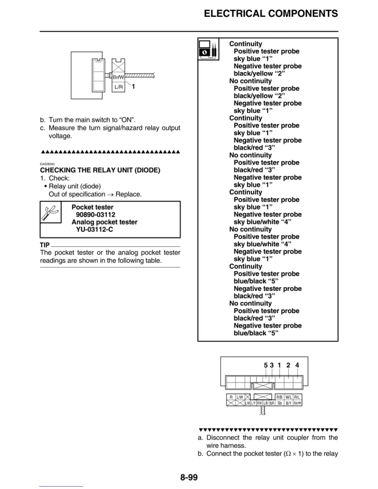
b. Turn the ma
in
swi
tc
h to "ON
".
c. Measure the turn signal/hazard relay output
voltage.
··-
CHECKING THE RELAY UNIT (DIODE)
1.
Ch
eck:
• Relay unit (diode)
Ou
t of specification
->
Replace.
Pocket tester
90890-03112
Analog
pocket
tester
YU-03112-C
TIP
---------------
The poc
ke
t tester or the analog pocket tester
readings are
sh
own in the
fo
ll
owing table.
ELECTRICAL COMPONENTS
Continuity
Positive tester probe
sky
blue "1"
Negative tester probe
black/yellow "2"
No
continuity
Positive tester probe
black/yellow
"2"
Negative tester probe
sky
blue "1"
Continuity
Positive tester probe
sky
blue "1"
Negative tester probe
black/red "3"
No
continuity
Positive tester probe
black/red "3"
Negative tester probe
sky
blue "1"
Continuity
Positive tester probe
sky
blue "1"
Negative tester probe
sky
blue/white "4"
No
cont
i
nuity
Positive tester probe
sky
blue/white "4"
Negative tester probe
sky
blue "1"
Continuity
Positive tester probe
blue/black "5"
Negative tester probe
black/red "3"
No
continuity
A
"'
Positive tester probe
black/red " 3"
Negative tester probe
blue/black "5"
~ ~
1
~
1
n I I I
Il
' ' '
UV/
I I
R'B
IWL
Rl
...,..
'UV
1,
..
~el
RR
Sb
B
IY
SblW
,
'
-
••••••••••••••••••••••••••••••••
a. Disconnect the relay unit
co
upler from the
wi
re
harness.
b. Connect the pocket tester
(!1 x 1) to the
re
lay
8-99



 To Next Page