b. Measure the accelerator position sensor
maximum resistance.
••••••••••••••••••••••••••••••••
3. Install:
• Accelerator position sensor
TIP
~~~~~~~~~~~~~~
When insta
lli
ng t
he
accelerator position sensor,
adjust its angle properly. Refer to "ADJU
ST
ING
THE ACCELERATOR POSITION SENSOR" on
page
7-13.
EAS1RCl81»
CHECKING THE
THROTILE
SERVO MOTOR
1. Remove:
• Air filter case
Refer to "GENERAL CHASSIS" on page 4-1.
2. Chec
k:
• Throttle valve operation
Throttle valves
do
not fully close
-t
Replace
the throttle bodies.
••••••••••••••••••••••••••••••••
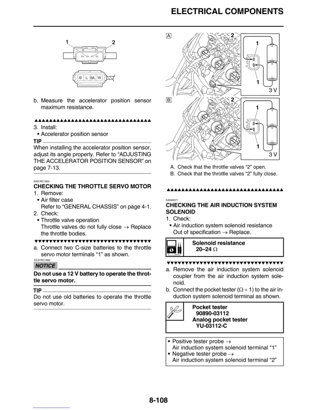
a. Connect two C-size batte
ri
es to the throttle
servo motor terminals "1" as shown.
ECAIRC\802
NOTICE
~~~~~~~~~~~~-
Do
not
use
a 12 V battery
to
operate
the
throt-
tle
servo
motor.
TIP
---------------
Do not use old batte
ri
es to operate the throttle
servo motor.
ELECTRICAL COMPONENTS
+
3V
+
3V
A. Check that the throttle valves "2" open.
B. Check that the throttle valves "2"
f
ully
close.
CHECKING THE AIR INDUCTI
ON
SYSTEM
SOLENO
ID
1.
Check:
• Air
in
duction system solenoid resistance
Out
of
specification
-t
Replace.
'~'
Solenoid resistance
20-24
0
TTTTTTTTTTTTTTTTTTTTTTTTTTTTTTTT
a. Remove the air induction system solenoid
coupler from the air induction system sole-
no
id.
b.
Connect t
he
pocket tester
(n
x 1)
to
the air in-
duction system solenoid terminal as shown.
Pocket
tester
90890-03112
Analog
pocket
t
es
t
er
YU
-03112-C
• Positive tester probe
-t
Air induction system solenoid terminal "1"
• Negative tester probe
-t
Air induction system solenoid terminal "2"
8-108