Rectifier/regulator
input
voltage
above
14
Vat
5000 r/
min
TTTTTTTTTTTTTTTTTTTTTTTTTTTTTTTT
a. Set
th
e eng
in
e tachometer to the igni
ti
on co
il
of cyl
in
der #1.
b. Connect t
he
pocket tester (AC 20 V) to t
he
rec
ti
fier/regulator coupler as shown.
Pocket
tester
90890-03112
Analog
pocket
tester
YU-03112-C
• Posi
ti
ve
tester probe
white "1"
• Negative tester
pr
obe
white "2"
• Posi
ti
ve
tester probe
white "1"
• Negative tester probe
white "3"
• Positi
ve
tester probe
white "2"
• Negative tester pr
obe
white "3"
1 2 3
\
1--
-1
~
c. Start the engine and let it run at approximate-
ly 5000 r/mi
n.
d. M
ea
sure the rectifier/regulator input voltag
e.
••••••••••••••••••••••••••••••••
2. Check:
• Rectifi
er
/regulator output voltage
Out
of
specification 4 Replace t
he
rec
ti
fi-
er/regulator.
Regulated voltage (DC)
14.3- 14.7
v
TTTTTTTTTTTTTTTTTTTTTTTTTTTTTTTT
a. Set
th
e eng
in
e tachometer to the ignition co
il
of cyl
in
der #1.
b. Connect the pocket tester (DC 20
V)
to the
battery as shown.
ELECTRICAL COMPONENTS
Pocket
tester
90890-03112
Analog
pocket
tester
YU
-03112-C
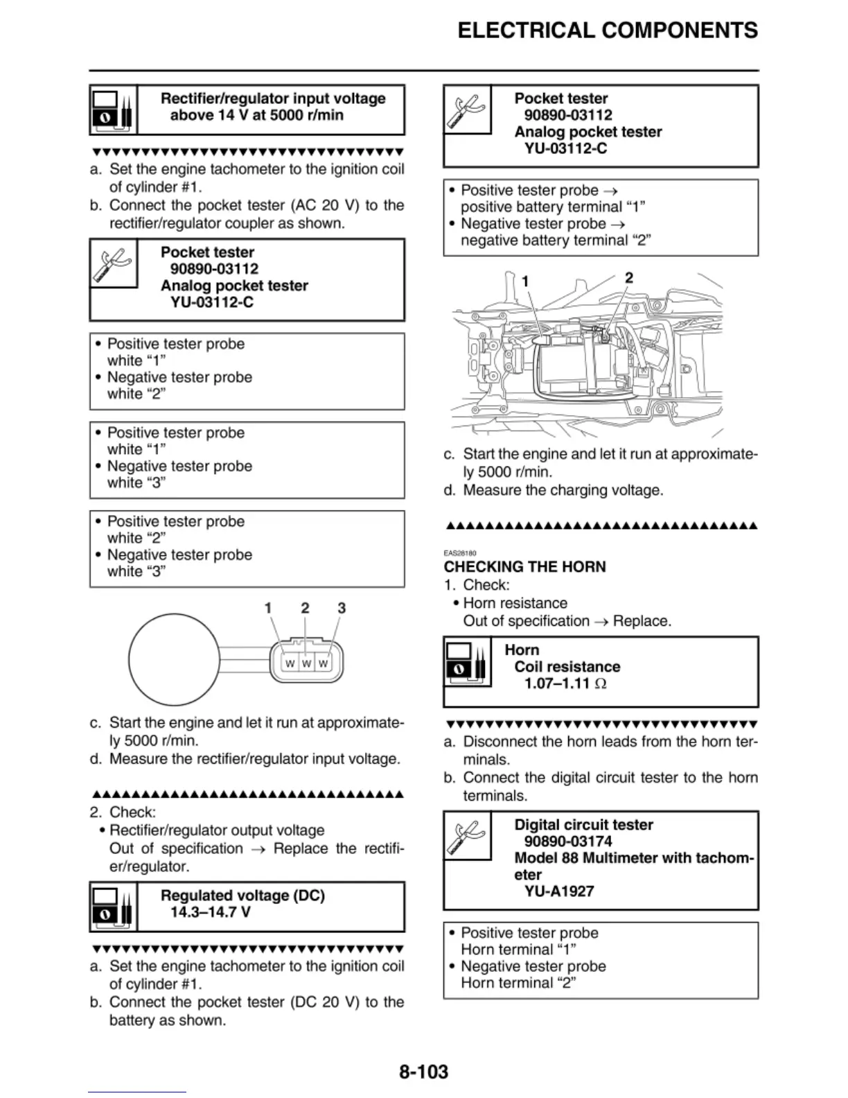
• Positive tester probe
4
positive
ba
ttery terminal "1"
• Negative tester probe
4
negative
ba
ttery terminal "2"
s,
'\*C
c. Sta
rt
the eng
in
e and let it run at approximate-
ly
5000 r/min.
d.
Me
asure the charging voltage.
.........
CHECKING THE HORN
1. Check:
• Hom resista
nc
e
O
u1
of
specification 4 Replace.
Horn
Coil resistance
1.01- 1.11
n
TTTTTTTTTTTTTTTTTTTTTTTTTTTTTTTT
a. Disconnect the ho
rn
leads from t
he
horn te
r-
minal
s.
b.
Connect the digital circuit tester to the horn
terminals .
Digital
circuit
tester
90890-03174
Model 88 Multimeter
with
tachom-
eter
YU-A1927
• Positive tester p
ro
be
Horn terminal "1"
• Negative tester probe
Horn terminal "2"
8-103