5-24
CAMSHAFTS
b. Lock the timing chain tensioner rod by set-
ting the circlip “4” into groove “5” while
pushing the timing chain tensioner rod.
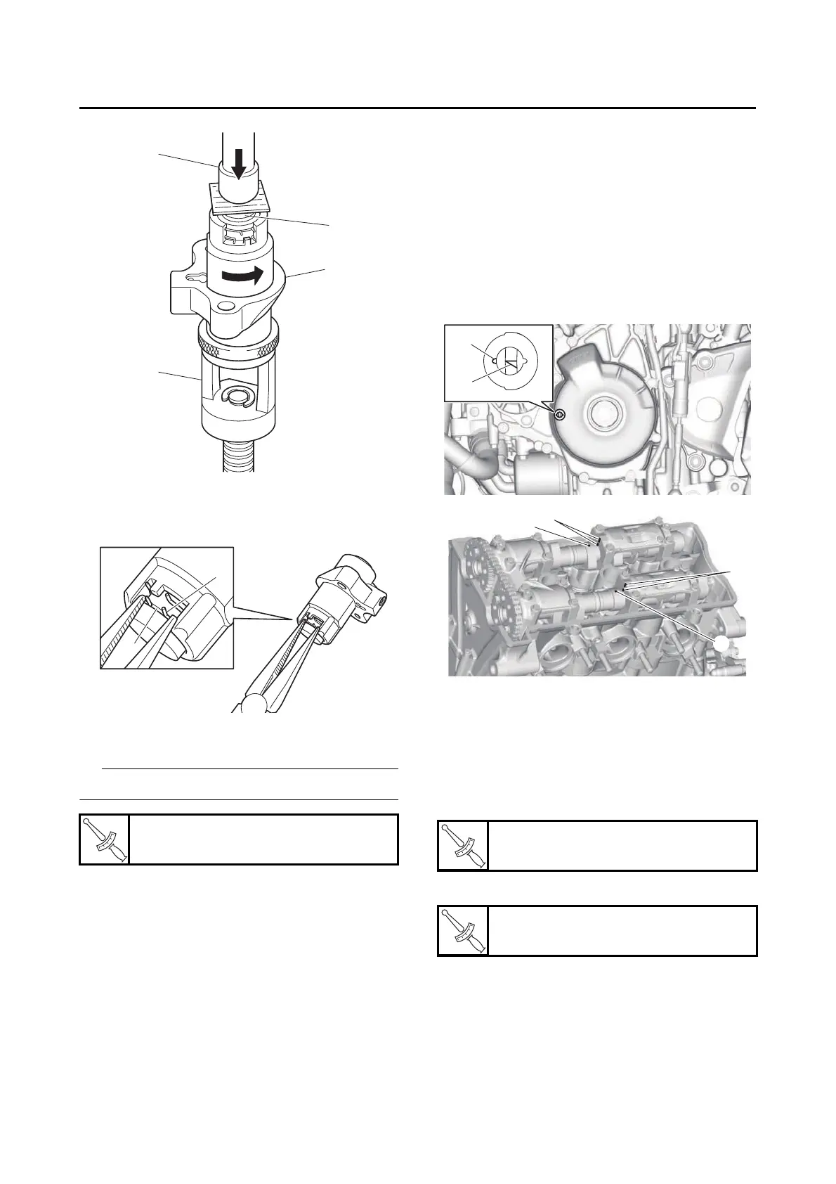
c. Install the timing chain tensioner to the cyl-
inder block.
Always use a new gasket.
d. Turn the crankshaft clockwise several times
to release the timing chain tensioner rod.
10.Turn:
• Crankshaft
(several turns counterclockwise)
11.Confirm the timing chain tension properly.
12.Check:
•Mark “a”
Make sure the mark “a” on the generator rotor
is aligned with the generator rotor cover mark
“b”.
• Camshaft punch mark “c”
Make sure the camshaft punch mark “c” on
the camshaft is aligned with the camshaft cap
alignment mark “d”.
Out of alignment → Adjust.
Refer to the installation steps above.
13.Measure:
• Valve clearance
Out of specification → Adjust.
Refer to “ADJUSTING THE VALVE CLEAR-
ANCE” on page 3-5.
14.Install:
• Timing mark accessing bolt “1”
• Crankshaft end cover “2”
Timing chain tensioner bolt
10 N·m (1.0 kgf·m, 7.4 lb·ft)
Timing mark accessing bolt
15 N·m (1.5 kgf·m, 11 lb·ft)
Crankshaft end cover
10 N·m (1.0 kgf·m, 7.4 lb·ft)