9-168
P0458
• Short circuit check
Disconnect the ECU related connectors before checking.
Refer to “REPLACING THE ECU (Engine Control Unit)” on page 8-56.
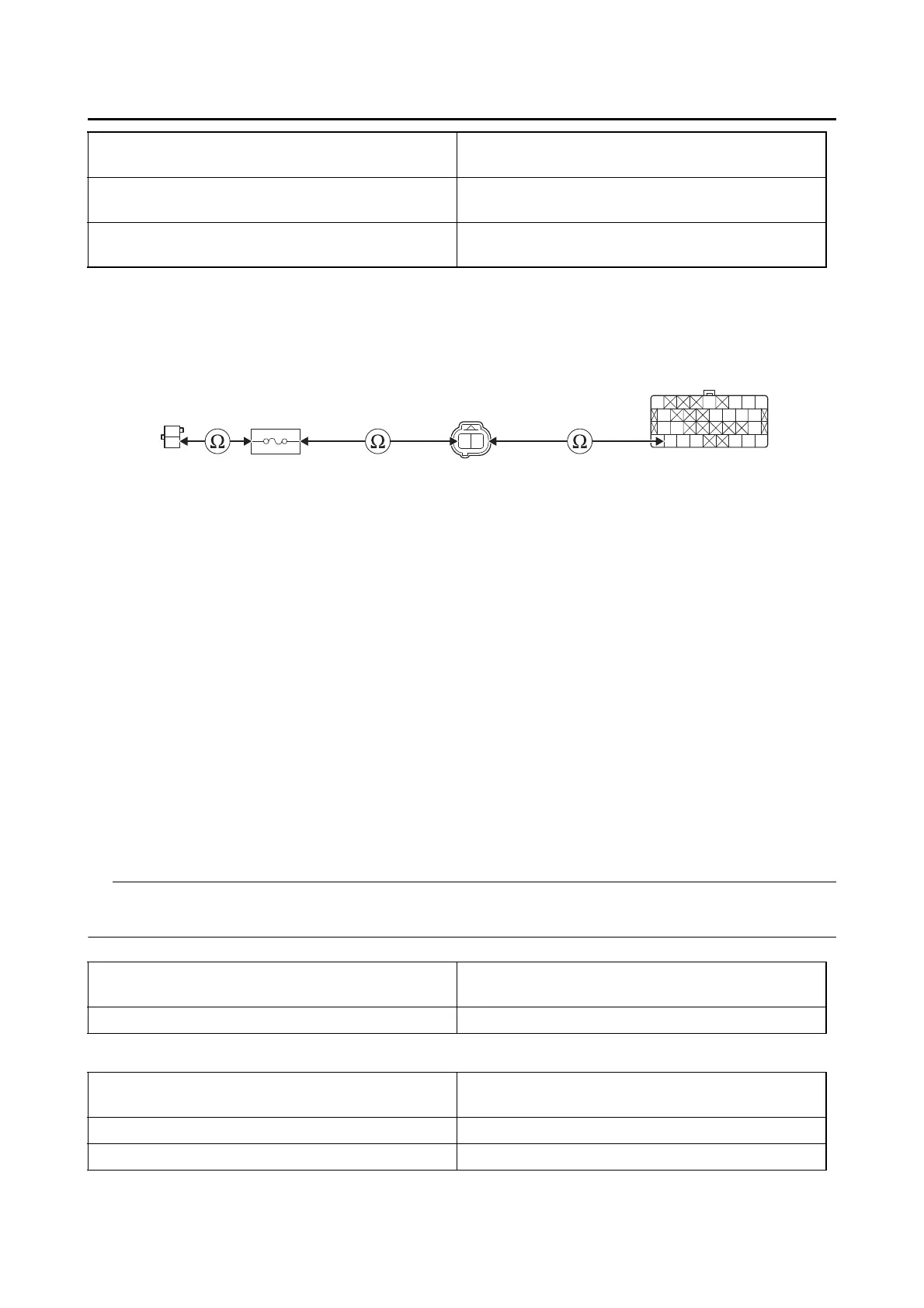
Ground short circuit check “A”
Lines short circuit check “B”
Between ignition fuse 1 holder “1” and purge cut
valve solenoid coupler “2”
red–red/white
Between purge cut valve solenoid coupler “2”
and ECU coupler “3”
yellow/red–yellow/red
Between main switch coupler “4” and ignition
fuse 1 holder “1”
brown/blue–brown/blue
Is resistance 0 Ω?
YES
→ Go to “Short circuit check”.
NO
a. Replace the wire harness.
b. Turn the main switch to “ON”, and then check the condition of the DTC using the malfunction
mode of the YDT.
Is it in the “Recovered” condition?
YES
→ Go to step 7, and complete the service.
NO
→ Go to “Short circuit check”.
Between purge cut valve solenoid coupler “2”
and ground
red/white–ground
yellow/red–ground
Between main switch coupler “4” and ground brown/blue–ground
Purge cut valve solenoid coupler “2”
red/white–any other coupler terminal
yellow/red–any other coupler terminal
ECU coupler “3” yellow/red–any other coupler terminal
Main switch coupler “4” brown/blue–any other coupler terminal
Y/RR/W
O
Gy/RO/GP/BY/R
B
R/BG/BL/BLg/R
B
G/YR/L
B/WB/WR/LL/WY/BY/RR/G
R
Br/L
2314
 Loading...


